

Review of Intentional Electromagnetic Interference on UAV Sensor Modules and Experimental Study
- PMID: 35336557
- PMCID: PMC8950540
- DOI: 10.3390/s22062384
Review of Intentional Electromagnetic Interference on UAV Sensor Modules and Experimental Study
Abstract
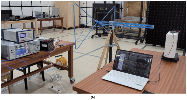
With the advancement of technology, Unmanned Aerial Vehicles (UAVs), also known as drones, are being used in numerous applications. However, the illegal use of UAVs, such as in terrorism and spycams, has also increased, which has led to active research on anti-drone methods. Various anti-drone methods have been proposed over time; however, the most representative method is to apply intentional electromagnetic interference to drones, especially to their sensor modules. In this paper, we review various studies on the effect of intentional electromagnetic interference (IEMI) on the sensor modules. Various studies on IEMI sources are reviewed and classified on the basis of the power level, information needed, and frequency. To demonstrate the application of drone-sensor modules, major sensor modules used in drones are briefly introduced, and the setup and results of the IEMI experiment performed on them are described. Finally, we discuss the effectiveness and limitations of the proposed methods and present perspectives for further research necessary for the actual application of anti-drone technology.
Keywords: UAV; anti-drone; drone; intentional electromagnetic interference; sensor module.
Conflict of interest statement
The authors declare no conflict of interest.
Figures


Similar articles
-
A dataset for multi-sensor drone detection.Data Brief. 2021 Oct 27;39:107521. doi: 10.1016/j.dib.2021.107521. eCollection 2021 Dec. Data Brief. 2021. PMID: 34765710 Free PMC article.
-
Advances and Challenges in Drone Detection and Classification Techniques: A State-of-the-Art Review.Sensors (Basel). 2023 Dec 26;24(1):125. doi: 10.3390/s24010125. Sensors (Basel). 2023. PMID: 38202987 Free PMC article. Review.
-
Analysis on security-related concerns of unmanned aerial vehicle: attacks, limitations, and recommendations.Math Biosci Eng. 2022 Jan 10;19(3):2641-2670. doi: 10.3934/mbe.2022121. Math Biosci Eng. 2022. PMID: 35240800
-
Analyzing unmanned aerial vehicle (drone) attacks; a disaster medicine perspective.Am J Emerg Med. 2024 Oct;84:135-140. doi: 10.1016/j.ajem.2024.08.001. Epub 2024 Aug 3. Am J Emerg Med. 2024. PMID: 39116674
-
Targeted Applications of Unmanned Aerial Vehicles (Drones) in Telemedicine.Telemed J E Health. 2018 Nov;24(11):833-838. doi: 10.1089/tmj.2017.0289. Epub 2018 Feb 28. Telemed J E Health. 2018. PMID: 29489441 Review.
Cited by
-
Planar Electrically Large Structures of Carbon Nanotube Films with High Absorption and Shielding Performance in X-Band.Sensors (Basel). 2025 Jun 25;25(13):3943. doi: 10.3390/s25133943. Sensors (Basel). 2025. PMID: 40648201 Free PMC article.
-
Research on Random Drift Model Identification and Error Compensation Method of MEMS Sensor Based on EEMD-GRNN.Sensors (Basel). 2022 Jul 13;22(14):5225. doi: 10.3390/s22145225. Sensors (Basel). 2022. PMID: 35890904 Free PMC article.
-
Predicting EMI in UAVs using characteristic mode analysis: a case study of the DJI Phantom 4.Sci Rep. 2025 Mar 23;15(1):10016. doi: 10.1038/s41598-025-94415-1. Sci Rep. 2025. PMID: 40122929 Free PMC article.
References
-
- Zhilenkov A.A., Epifantsev I.R. System of autonomous navigation of the drone in difficult conditions of the forest trails; Proceedings of the 2018 IEEE Conference of Russian Young Researchers in Electrical and Electronic Engineering (EIConRus); Moscow, Russia. 29 January–1 February 2018; pp. 1036–1039. - DOI
-
- Hodge V.J., Hawkins R., Alexander R. Deep reinforcement learning for drone navigation using sensor data. Neural Comput. Appl. 2021;33:2015–2033. doi: 10.1007/s00521-020-05097-x. - DOI
-
- Zhang C., Zhang W. Spectrum Sharing for Drone Networks. IEEE J. Sel. Areas Commun. 2017;35:136–144. doi: 10.1109/JSAC.2016.2633040. - DOI
-
- Shrit O., Martin S., Alagha K., Pujolle G. A new approach to realize drone swarm using ad hoc network; Proceedings of the 2017 16th Annual Mediterranean Ad Hoc Networking Workshop (Med-Hoc-Net); Budva, Montenegro. 28–30 June 2017; pp. 1–5. - DOI
-
- Dijkshoorn N., Visser A. Integrating Sensor and Motion Models to Localize an Autonomous AR.Drone. Int. J. Micro Air Veh. 2011;3:183–200. doi: 10.1260/1756-8293.3.4.183. - DOI
Publication types
Grants and funding
LinkOut - more resources
Full Text Sources
