Review
. 2022 Apr 11;8(4):1381-1395.
doi: 10.1021/acsbiomaterials.1c01509. Epub 2022 Mar 31.

Digital Light Processing Bioprinting Advances for Microtissue Models

Affiliations
Review

Digital Light Processing Bioprinting Advances for Microtissue Models

Hossein Goodarzi Hosseinabadi et al. ACS Biomater Sci Eng. .

Abstract

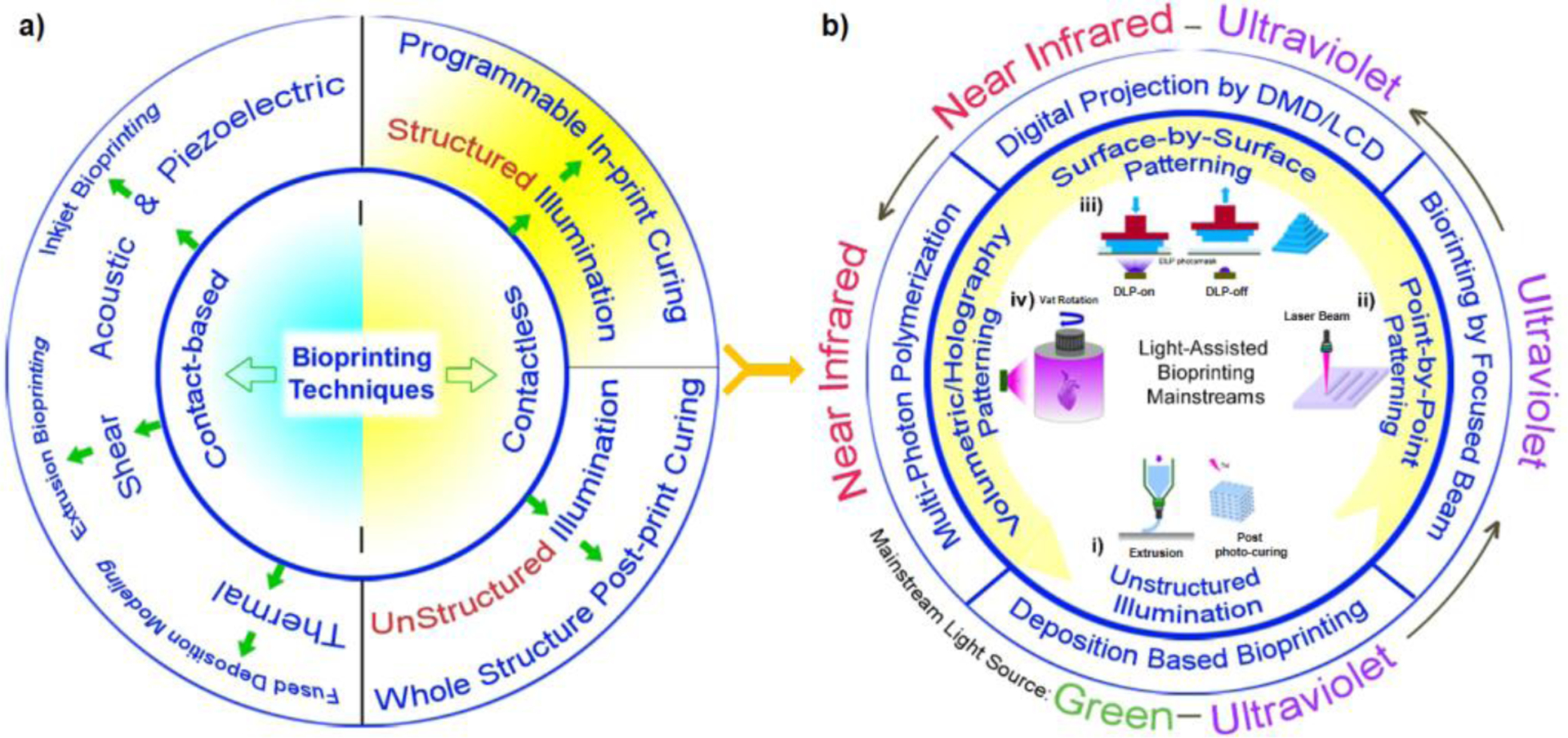
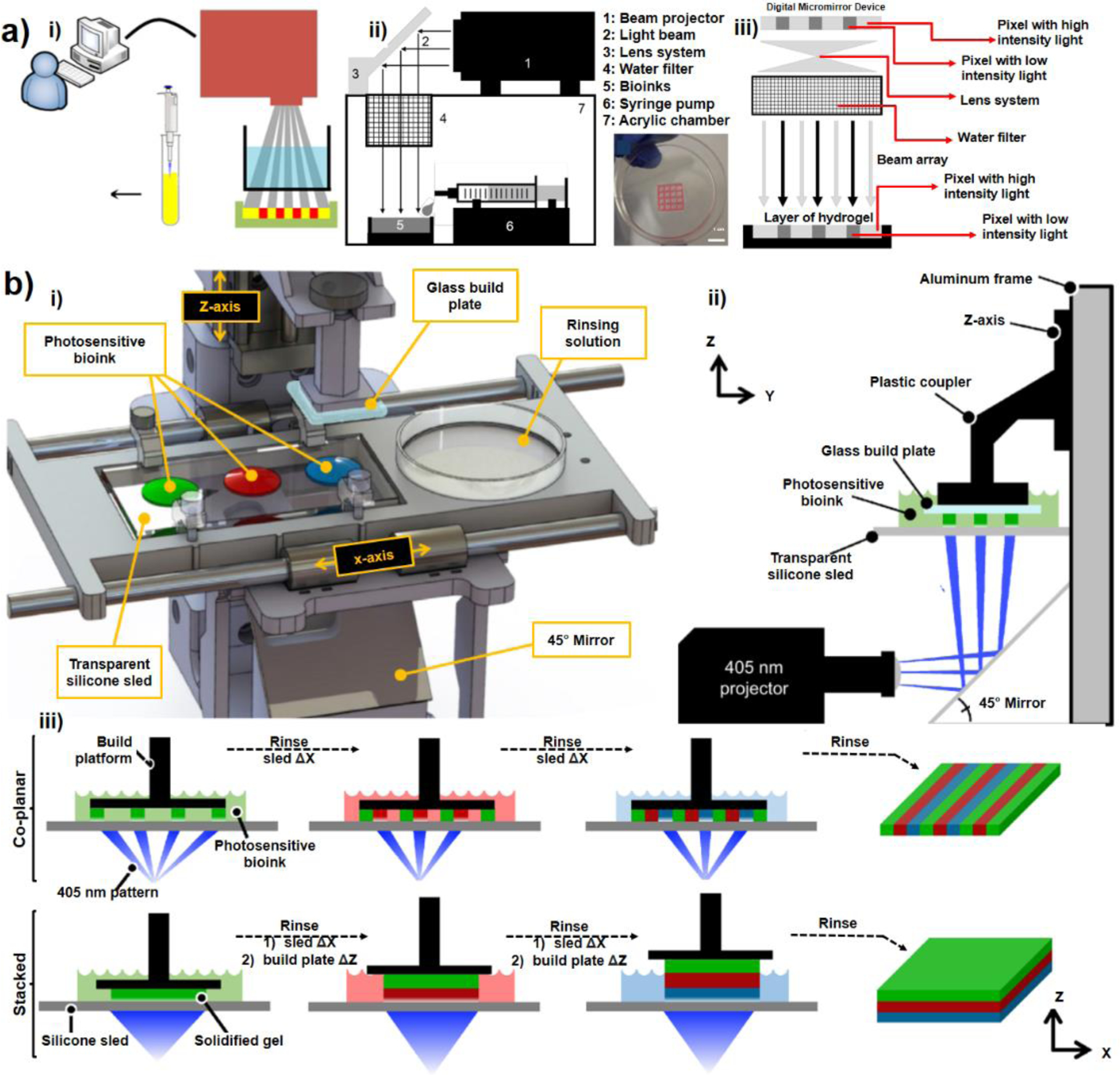
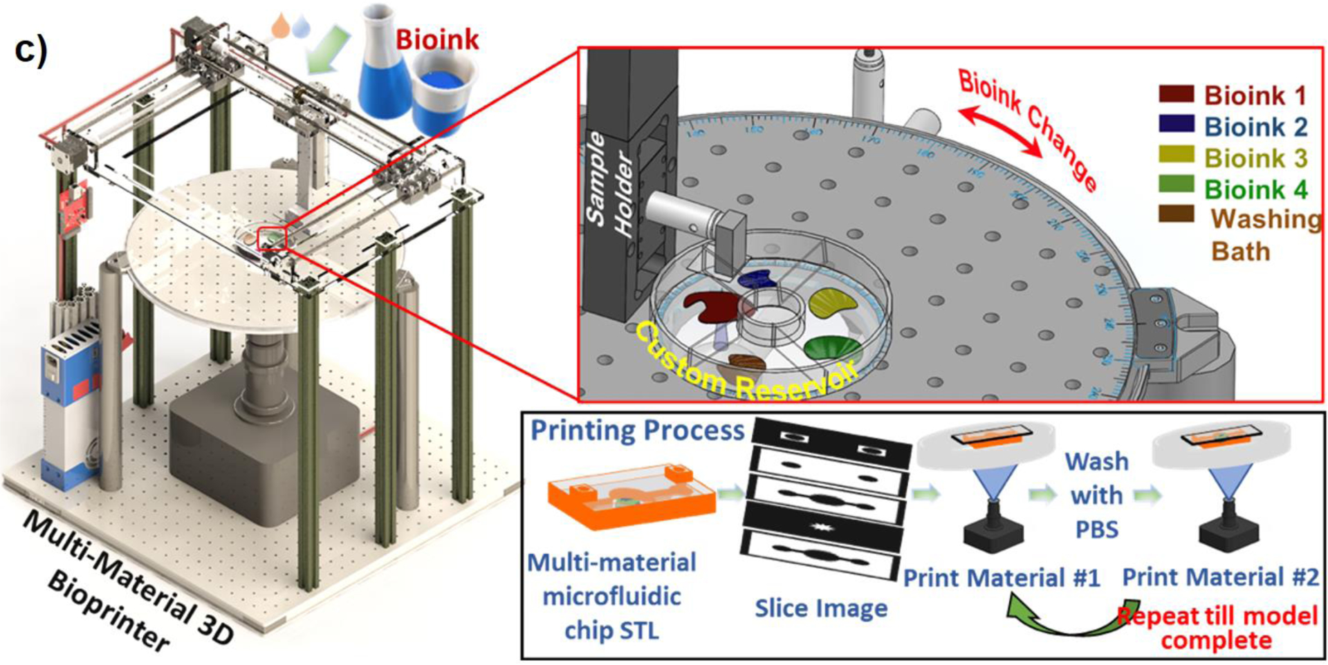
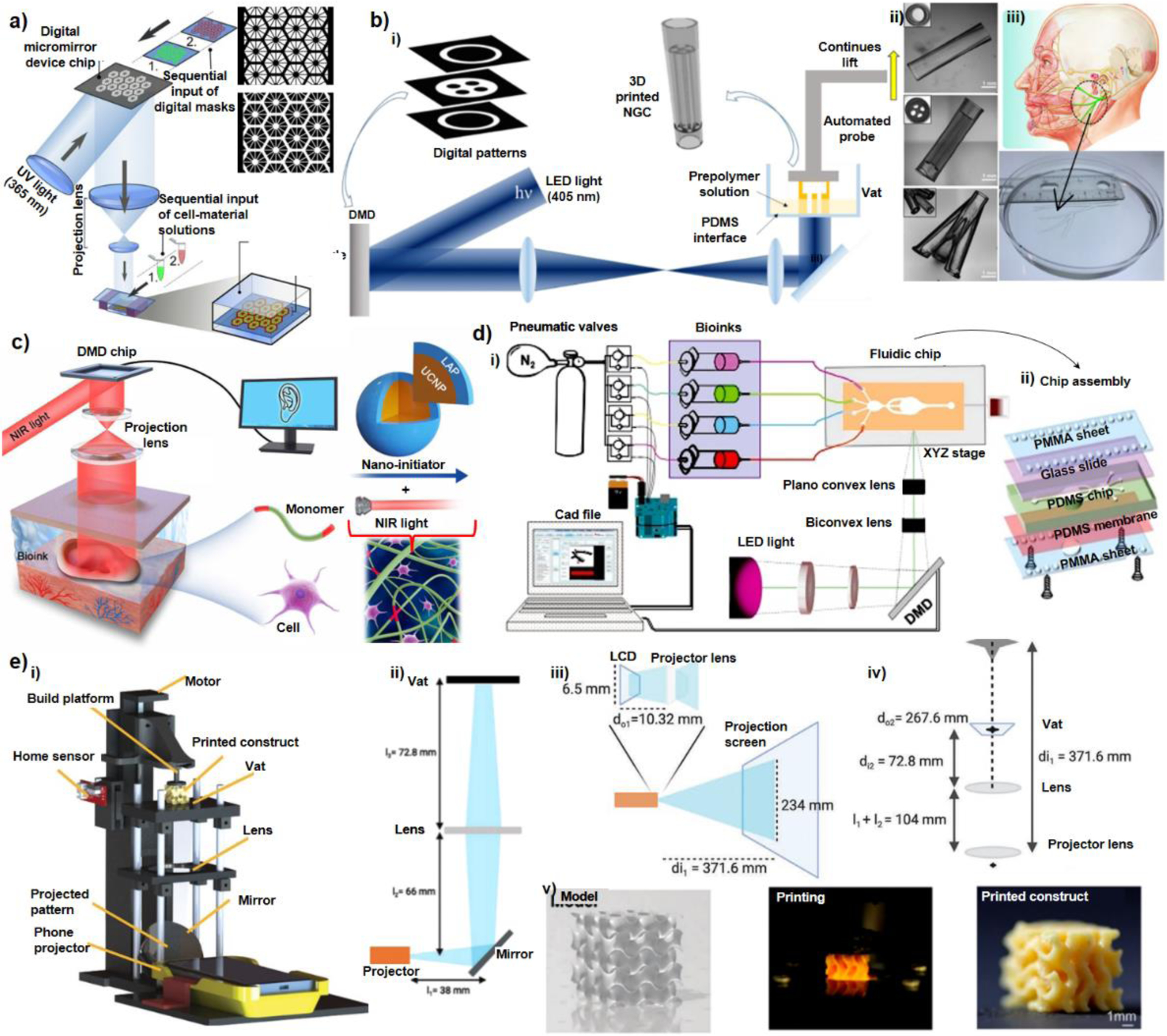
Digital light processing (DLP) bioprinting has been widely introduced as a fast and robust biofabrication method in tissue engineering. The technique holds a great promise for creating tissue models because it can replicate the resolution and complexity of natural tissues and constructs. A DLP system projects 2D images onto layers of bioink using a digital photomask. The resolution of DLP bioprinting strongly depends on the characteristics of the projected light and the photo-cross-linking response of the bioink microenvironment. In this review, we present a summary of DLP fundamentals with a focus on bioink properties, photoinitiator selection, and light characteristics in resolution of bioprinted constructs. A simple guideline is provided for bioengineers interested in using DLP platforms and customizing technical specifications for its design. The literature review reveals the promising future of DLP bioprinting for disease modeling and biofabrication.

Keywords: bioprinter design; digital light processing; tissue engineering; vascularized models.


Conflict of interest statement

Conflict of Interest

Authors declare no Conflict of Interest.

Figures

Figure 1.
Figure 1.
a) Common bioprinting methods used for creating micro-tissue models and scaffolds, and b) light-assisted bioprinting methods showing: i) unstructured illumination of a printed construct followed by a post-print photocuring, ii) point-by-point bioprinting using a focused laser beam, iii) surface-by-surface light patterning using DLP devices composed of digital micro-mirror devices or LCDs as a light mask, iv) volumetric light patterning in multi-photon polymerization techniques using a near infrared beam. The type of light which has found widespread applications in each category is shown.
Figure 2.
Figure 2.
Variations of the absorption by wavelength for different concentrations of PIs including a) LAP, b) VA086, in water solution obtained by plate reader.
Figure 3-
Figure 3-. DLP Bioprinters Based on Commercial DLP:
a) A simple stereolithography-based 3D bioprinting system developed for crosslinking bioinks with high intensity white light. i) the binary patterns were directly transferred to the bioinks (red areas in the picture) layer by layer , , ii) a mirror (lens system) is used to transfer the patterned light, iii) demonstration of DMD capabilities for grayscale patterning to change the light intensity on each pixel; (Reproduced with permission from ref. Copyright 2015 IOP Publishing), b) Design of a multi-material stereolithography bioprinter: i) Perspective view rendering of bioprinter components, where a motorized silicone sled translates laterally in the X-axis to automate bioink selection and rinsing, ii) Side view schematic showing the glass build plate lowered into a bioink droplet, creating a thin first layer (50 μm) for photocrosslinking, iii) Print workflow for fabricating hydrogels. The motorized sled allows nascent structures to interface with separate bioinks of variable chemical or cellular composition, providing heterogeneity within individuals layer (co-planar; XY) and across sequential layers (stacked; Z), (Reprinted with permission from ref . Copyright 2021 Springer Nature), c) Design of a customized bioprinter using a commercial DLP box and multi-material module for creating hydrogel constructs: left picture shows the whole apparatus with x-y-z stage for large constructs and right pictures show the rotation model used to exchange materials on a UV-glass substrate (Reprinted with permission from ref . Copyright 2021 IOP Publishing).
Figure 4-
Figure 4-. Custom-Built DLP Bioprinters:
a) Schematic of a two-step bioprinting approach for patterning the first grayscale digital mask (top) for lobule structure followed by the patterning of second grayscale digital mask (down) for vascular structure (Reprinted with permission from ref . Copyright 2016 National Academy of Sciences), b) Schematic of the rapid continuous 3D-printer, i) printing customizable nerve guidance conduits (NGCs) with inclusion of a motorized stage, ii) various 3D-printed NGC structures, iii) 3D-printed human life-size NGC based on the facial nerve schematic adapted from Atlas of Human Anatomy (Reprinted with permission from ref . Copyright 2018 Elsevier), c) Schematic of digital near-infrared based noninvasive bioprinter: the DMD chip reflects 980 nm light with a pattern across optical lens, onto the bioink, which was injected into the body to noninvasively fabricate a living tissue in vivo. The bioink contains UCNP@LAP nanoinitiators that can convert the NIR light to 365 nm light and thus initiates the pattern–controlled polymerization (Reprinted with permission from ref . Copyright 2020 AAAS), d) Planar schematics of the multi-material stereolithographic bioprinter including i) UV lamp, optical lenses, DMD chip, pneumatic module and the microfluidic device, ii) the assembly of the microfluidic chip having four inlets and one common outlet (Reprinted with permission from ref . Copyright 2018 Wiley-VCH), e) Smart phone enabled bioprinter, i) schematic diagram of the bioprinter, ii) diagram of the optical relationship between the projector, the mirror, the lens, and the vat; iii) the optical path inside the smartphone-powered projector; iv) the calculation of magnification between the projector lens and the vat, v) an example of a gyroid printing from the 3D model to the printed construct (Reprinted with permission from ref . Copyright 2021 Elsevier).
Figure 5.
Figure 5.. Various Bioprinted Tissue Constructs:
a) Bioprinted 3D triculture construct. i) Bioprinted hepatic construct on a piece of coverslip held by a pair of forceps. (Scale bar, 5 mm.) ii) 3D reconstruction of the construct showing the patterns of hepatic cells (green) and supporting cells (red). (Scale bar, 500 μm) (Reprinted with permission from ref . Copyright 2020 Elsevier); b) i) A tendon-to-bone insertion model showing the schematic of the tendon-to-bone insertion site; the mask for printing; bright-field optical image showing a bioprinted dye-laden GelMA structure; bioprinted structure of GelMA containing patterned osteoblasts (blue), MSCs (red), and fibroblasts (green); the inset shows a magnified image of the region hosting fibroblasts, where the cells were stained for f-actin (green) and nuclei (blue). ii) A tumor angiogenesis model showing schematic showing the tumor angiogenesis model; the mask for printing; bioprinted microvasculature in PEGDA; bioprinted MCF7 cell (blue)-laden microvascular bed of GelMA further seeded with HUVECs (green) in the channels (Reprinted with permission from ref . Copyright 2018 Wiley-VCH), c) Engraftment of functional hepatic hydrogel carriers and vascularized alveolar models i) Prevascularized hepatic hydrogel carriers created by seeding endothelial cells (HUVECs) in the vascular network post-bioprinting. ii) Confocal microscopy observations show that hydrogel anchors physically entrap fibrin gel containing the hepatocyte aggregates (Hep) (scale bar, 1 mm). iii) Tidal ventilation and oxygenation in hydrogels with vascularized alveolar model topologies (Reprinted with permission from ref . Copyright 2019 Springer Nature). d) Bioprinted hydrogel-based microfluidic chips: i) A ready-to-use microfluidic chip made of PEGDA and GelMA. ii) Vascular modelling in bioprinted microfluidic chip: fluorescence images showing HUVECs stained for F-actin (green) and nuclei (blue) at Day 10 (left); and fluorescence images showing HUVECs stained for CD31 (red) and nuclei (blue) at Day 10 (right) (Adapted with permission from ref . Copyright 2021 IOP Publishing). e) Micropatterning of cardiac tissue and effects on displacement. i) 3D schematic of full tissue-measuring scaffold and confocal 3D reconstruction of stained cardiac tissue. ii) Masks of various complex patterns and DIC images showing each patterned tissue at Day 10 (scale bar is 500 μm). iii) Fluorescent images of printed cardiac tissue stained for α-actinin for each scaffold type showing alignment of sarcomeres (scale bar is 25 μm) and summary of max displacement for various patterned tissues at 1, 2, and 4 Hz (Reprinted with permission from ref . Copyright 2020 Elsevier).

References

    1. Bhatia SN; Ingber DE Microfluidic Organs-on-Chips. Nat. Biotechnol 2014, 32 (8), 760–772. - PubMed
    1. Dodd RD; Mito JK; Kirsch DG Animal Models of Soft-Tissue Sarcoma. DMM Dis. Model. Mech 2010, 3 (9–10), 557–566. - PMC - PubMed
    1. Cox TR; Erler JT Remodeling and Homeostasis of the Extracellular Matrix: Implications for Fibrotic Diseases and Cancer. DMM Dis. Model. Mech 2011, 4 (2), 165–178. - PMC - PubMed
    1. Stylianopoulos T; Munn LL; Jain RK Reengineering the Physical Microenvironment of Tumors to Improve Drug Delivery and Efficacy: From Mathematical Modeling to Bench to Bedside. Trends in Cancer 2018, 4 (4), 292–319. - PMC - PubMed
    1. Kuo C. Te; Chiang CL; Huang RYJ; Lee H; Wo AM Configurable 2D and 3D Spheroid Tissue Cultures on Bioengineered Surfaces with Acquisition of Epithelial-Mesenchymal Transition Characteristics. NPG Asia Mater. 2012, 4 (9), 1–8.

Publication types

LinkOut - more resources