. 2022 Apr 8;8(14):eabm8162.
doi: 10.1126/sciadv.abm8162. Epub 2022 Apr 6.

Twin-free, directly synthesized MFI nanosheets with improved thickness uniformity and their use in membrane fabrication

Affiliations

Twin-free, directly synthesized MFI nanosheets with improved thickness uniformity and their use in membrane fabrication

Donghun Kim et al. Sci Adv. .

Abstract

Zeolite nanosheets can be used for the fabrication of low-defect-density, thin, and oriented zeolite separation membranes. However, methods for manipulating their morphology are limited, hindering progress toward improved performance. We report the direct synthesis (i.e., without using exfoliation, etching, or other top-down processing) of thin, flat MFI nanosheets and demonstrate their use as high-performance membranes for xylene isomer separations. Our MFI nanosheets were synthesized using nanosheet fragments as seeds instead of the previously used MFI nanoparticles. The obtained MFI nanosheets exhibit improved thickness uniformity and are free of rotational and MEL intergrowths as shown by transmission electron microscopy (TEM) imaging. The nanosheets can form well-packed nanosheet coatings. Upon gel-free secondary growth, the obtained zeolite MFI membranes show high separation performance for xylene isomers at elevated temperature (e.g., p-xylene flux up to 1.5 × 10⁻³ mol m-2 s-1 and p-/o-xylene separation factor of ~600 at 250°C).


Figures
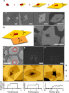
Fig. 1.
Fig. 1.. Rectangular outgrowth of zeolite MFI nanosheet.
(A) Schematic and the corresponding SEM images of the sequence leading to MFI rhombus-shaped nanosheets, as reported in (30). (B) Schematic of the rectangular outgrowth and (C) corresponding representative SEM image. (D) Low-magnification TEM image and (E and F) selected area diffraction patterns of nanocrystal-seeded zeolite MFI nanosheet. An overlaid outline of the nanosheet and outgrowth is shown in fig. S2. The rhombus nanosheet and rectangular outgrowth have identical crystal orientations, as confirmed by their corresponding SAED shown in (E) and (F), respectively. (G to I) AFM images of nanocrystal-seeded zeolite MFI nanosheets with rectangular outgrowths and corresponding height profiles extracted from the dotted lines showing 2-nm step at rhombus/outgrowth boundary. Scale bars from left to right in (A), 200 nm, 200 nm, 500 nm, and 1 μm. Scale bars, 1 μm (C), 1 μm (D), 1 nm−1 (E and F), 1 μm (G to I).
Fig. 2.
Fig. 2.. Preparation of zeolite MFI nanosheet fragments.
(A) Schematic illustration of the preparation of flat zeolite MFI nanosheets. SEM images for (B) MFI nanocrystal seeds, (C) MFI nanosheets obtained using the seeds shown in (B), (D) fractured MFI nanosheets obtained by sonication of nanosheets shown in (C), and (E) MFI nanosheet fragments acquired after purification using centrifugation. The zeolite MFI nanocrystals shown in (B) were hydrothermally treated with a dC5–silica sol at 155°C to yield the MFI nanosheets shown in (C). The nanosheets in (C) were then fractured with a horn sonicator to yield the material shown in (D). After the purification with centrifugation, the nanosheet fragments shown in (E) were obtained. Details are described in Materials and Methods. Scale bars, 200 nm (B), 5 μm (C), 2 μm (D and E).
Fig. 3.
Fig. 3.. Characterization of novel zeolite MFI nanosheets.
(A to C) SEM images of the novel (nanosheet-seeded) zeolite MFI nanosheets synthesized from the secondary growth of nanosheet fragments. (D) A low-magnification TEM image, (E) Wiener-filtered HR-TEM image, and (F) SAED pattern of the novel zeolite MFI nanosheets. (G) Lateral size distributions (along the a and c axes) and (H) AFM height image of a typical novel zeolite MFI nanosheet. (I) Height profiles extracted from the dotted lines in (H). The nanosheets exhibit a rectangular shape with a small fraction having a rhombus shape [indicated by arrows in (A)]. Scale bars, 2 μm (A), 1 μm (B to D), 2 nm (E), 1 nm−1 (F), 1 μm (H).
Fig. 4.
Fig. 4.. Zeolite MFI nanosheet monolayer coating.
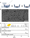
(A) Schematic illustration of the monolayer coating procedure of novel (nanosheet-seeded) zeolite MFI nanosheets using the floating particle coating method. (B) SEM image of as-synthesized novel zeolite MFI nanosheet monolayer on an Si wafer. (C) XRD patterns acquired from (i) a simulation for conventional zeolite MFI (TPA-silicalite-1), (ii) in-plane measurement for a monolayer coating of as-synthesized zeolite MFI nanosheets prepared by top-down processing based on exfoliation of multilamellar MFI using melt-blending, and (iii) in-plane measurement for a monolayer coating of as-synthesized novel zeolite MFI nanosheets. Scale bar, 10 μm (B). a.u., arbitrary unit.
Fig. 5.
Fig. 5.. Zeolite MFI membranes fabricated from nanosheet-seeded nanosheets and nanocrystal-seeded nanosheets.
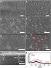
(A and B) SEM images of zeolite MFI nanosheet coatings on porous silica supports fabricated from (A) novel (nanosheet-seeded) MFI nanosheets and (B) previously reported nanocrystal-seeded MFI nanosheets. (C to F) SEM images of zeolite MFI membranes fabricated from multilayer coatings of (C and E) novel MFI nanosheets and (D and F) nanocrystal-seeded MFI nanosheets. The red arrows in (F) indicate a-oriented grains that are formed from the nanocrystal seeds used for the synthesis of nanosheets. (G) Cross-sectional SEM image and (H) XRD pattern of a zeolite MFI membrane fabricated from multilayer coating of novel zeolite MFI nanosheets. Scale bars, 5 μm (A and B), 2 μm (C and D), 1 μm (E and F), 2 μm (G).
Fig. 6.
Fig. 6.. Separation performance of zeolite MFI membranes for p-/o-xylene binary mixture.
(A) p-Xylene permeances and separation factors at various operation temperatures and (B) p-Xylene fluxes and separation factors at various p-xylene feed partial pressures (all mixtures with 1:1 p- and o-xylene) for a zeolite MFI membrane fabricated from a monolayer coating of novel (nanosheet-seeded) zeolite MFI nanosheets [membrane (D) in Table 1]. (C) Xylene isomer separation performance at 250°C for the zeolite MFI membranes reported here (○: membrane C, 7.7 kPa of p-xylene and 8.3 kPa of o-xylene in feed; ●: membrane C, 16 kPa of p-xylene and 1.7 kPa of o-xylene in feed; and ■: membrane D, 9.2 kPa of p-xylene and 9.9 kPa of o-xylene in feed) fabricated from the novel zeolite MFI nanosheets compared with other xylene isomer separation membranes from the literature [⬟: (30), ▽: (35), ★: (36), ▶: (40), ◀: (41), ▲: (42), ◁: (43) ▼: (55), and △: (56)]. The dotted line shows the upper boundary for the performances of representative MFI membranes reported earlier.

References

    1. Kondo M., Komori M., Kita H., Okamoto K., Tubular-type pervaporation module with zeolite NaA membrane. J. Membr. Sci. 133, 133–141 (1997).
    1. Carreon M. A., Li S., Falconer J. L., Noble R. D., Alumina-supported SAPO-34 membranes for CO2/CH4 separation. J. Am. Chem. Soc. 130, 5412–5413 (2008). - PubMed
    1. Okazaki J., Hasegawa H., Chikamatsu N., Yajima K., Shimizu K., Niino M., DDR-type zeolite membrane: A novel CO2 separation technology for enhanced oil recovery. Sep. Purif. Technol. 218, 200–205 (2019).
    1. Rangnekar N., Mittal N., Elyassi B., Caro J., Tsapatsis M., Zeolite membranes –A review and comparison with MOFs. Chem. Soc. Rev. 44, 7128–7154 (2015). - PubMed
    1. Sawamura K., Furuhata T., Sekine Y., Kikuchi E., Subramanian B., Matsukata M., Zeolite membrane for dehydration of isopropylalcohol–water mixture by vapor permeation. ACS Appl. Mater. Interfaces 7, 13728–13730 (2015). - PubMed