

Validating In Silico and In Vitro Patient-Specific Structural and Flow Models with Transcatheter Bicuspid Aortic Valve Replacement Procedure
- PMID: 35391657
- PMCID: PMC12087951
- DOI: 10.1007/s13239-022-00620-8
Validating In Silico and In Vitro Patient-Specific Structural and Flow Models with Transcatheter Bicuspid Aortic Valve Replacement Procedure
Abstract
Introduction: Bicuspid aortic valve (BAV) is the most common congenital cardiac malformation, which had been treated off-label by transcatheter aortic valve replacement (TAVR) procedure for several years, until its recent approval by the Food and Drug Administration (FDA) and Conformité Européenne (CE) to treat BAVs. Post-TAVR complications tend to get exacerbated in BAV patients due to their inherent aortic root pathologies. Globally, due to the paucity of randomized clinical trials, clinicians still favor surgical AVR as the primary treatment option for BAV patients. While this warrants longer term studies of TAVR outcomes in BAV patient cohorts, in vitro experiments and in silico computational modeling can be used to guide the surgical community in assessing the feasibility of TAVR in BAV patients. Our goal is to combine these techniques in order to create a modeling framework for optimizing pre-procedural planning and minimize post-procedural complications.
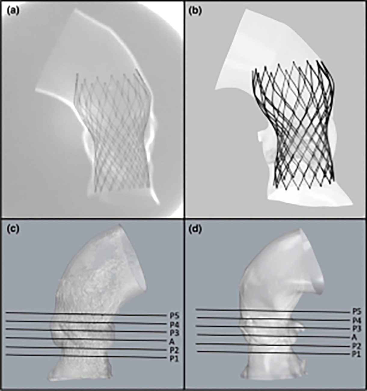
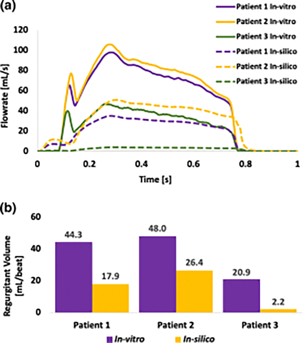
Materials and methods: Patient-specific in silico models and 3D printed replicas of 3 BAV patients with different degrees of post-TAVR paravalvular leakage (PVL) were created. Patient-specific TAVR device deployment was modeled in silico and in vitro-following the clinical procedures performed in these patients. Computational fluid dynamics simulations and in vitro flow studies were performed in order to obtain the degrees of PVL in these models.
Results: PVL degree and locations were consistent with the clinical data. Cross-validation comparing the stent deformation and the flow parameters between the in silico and the in vitro models demonstrated good agreement.
Conclusion: The current framework illustrates the potential of using simulations and 3D printed models for pre-TAVR planning and assessing post-TAVR complications in BAV patients.
Keywords: 3D printing; Aortic valve; Bicuspid aortic valve (BAV); Paravalvular leakage (PVL); Patient-specific computational modeling; Transcatheter aortic valve replacement (TAVR).
© 2022. The Author(s) under exclusive licence to Biomedical Engineering Society.
Conflict of interest statement
Conflict of Interest
Author DB has an equity interest in PolyNova Cardiovascular Inc. Author BK is a consultant of Polynova Cardiovascular Inc. All the other authors have no conflict of interest.
Figures


Similar articles
-
Assessment of Paravalvular Leak Severity and Thrombogenic Potential in Transcatheter Bicuspid Aortic Valve Replacements Using Patient-Specific Computational Modeling.J Cardiovasc Transl Res. 2022 Aug;15(4):834-844. doi: 10.1007/s12265-021-10191-z. Epub 2021 Dec 2. J Cardiovasc Transl Res. 2022. PMID: 34859367 Free PMC article.
-
Biomechanical modeling of transcatheter aortic valve replacement in a stenotic bicuspid aortic valve: deployments and paravalvular leakage.Med Biol Eng Comput. 2019 Oct;57(10):2129-2143. doi: 10.1007/s11517-019-02012-y. Epub 2019 Aug 1. Med Biol Eng Comput. 2019. PMID: 31372826 Free PMC article.
-
Treatment of Bicuspid Aortic Valve Stenosis with TAVR: Filling Knowledge Gaps Towards Reducing Complications.Curr Cardiol Rep. 2022 Jan;24(1):33-41. doi: 10.1007/s11886-021-01617-w. Epub 2022 Jan 31. Curr Cardiol Rep. 2022. PMID: 35099762 Review.
-
Designing a Novel Asymmetric Transcatheter Aortic Valve for Stenotic Bicuspid Aortic Valves Using Patient-Specific Computational Modeling.Ann Biomed Eng. 2023 Jan;51(1):58-70. doi: 10.1007/s10439-022-03039-3. Epub 2022 Aug 30. Ann Biomed Eng. 2023. PMID: 36042099 Free PMC article.
-
Transcatheter aortic valve replacement for bicuspid aortic valve stenosis with first- and new-generation bioprostheses: A systematic review and meta-analysis.Int J Cardiol. 2020 Jan 1;298:76-82. doi: 10.1016/j.ijcard.2019.09.003. Epub 2019 Sep 6. Int J Cardiol. 2020. PMID: 31575495
Cited by
-
Regulatory science promotes the translation of transcatheter tricuspid valve repair/replacement devices.Regen Biomater. 2024 Jul 18;11:rbae084. doi: 10.1093/rb/rbae084. eCollection 2024. Regen Biomater. 2024. PMID: 39220742 Free PMC article.
-
Mild Paravalvular Leak May Pose an Increased Thrombogenic Risk in Transcatheter Aortic Valve Replacement (TAVR) Patients-Insights from Patient Specific In Vitro and In Silico Studies.Bioengineering (Basel). 2023 Feb 1;10(2):188. doi: 10.3390/bioengineering10020188. Bioengineering (Basel). 2023. PMID: 36829682 Free PMC article.
-
Effect of Sinotubular Junction Size on TAVR Leaflet Thrombosis: A Fluid-Structure Interaction Analysis.Ann Biomed Eng. 2024 Mar;52(3):719-733. doi: 10.1007/s10439-023-03419-3. Epub 2023 Dec 14. Ann Biomed Eng. 2024. PMID: 38097896 Free PMC article.
-
Generation of a virtual cohort of TAVI patients for in silico trials: a statistical shape and machine learning analysis.Med Biol Eng Comput. 2025 Feb;63(2):467-482. doi: 10.1007/s11517-024-03215-8. Epub 2024 Oct 10. Med Biol Eng Comput. 2025. PMID: 39388030 Free PMC article.
-
The impact of bicuspid valve morphology on the selection of transcatheter aortic valve implantation devices: an in silico study.Eur Heart J Imaging Methods Pract. 2025 Feb 5;3(1):qyaf018. doi: 10.1093/ehjimp/qyaf018. eCollection 2025 Jan. Eur Heart J Imaging Methods Pract. 2025. PMID: 40041035 Free PMC article.
References
Publication types
MeSH terms
Grants and funding
LinkOut - more resources
Full Text Sources
