Review
. 2022 May 3;22(9):1650-1679.
doi: 10.1039/d1lc01168e.

Microscopic artificial cilia - a review

Affiliations
Review

Microscopic artificial cilia - a review

Tanveer Ul Islam et al. Lab Chip. .

Abstract

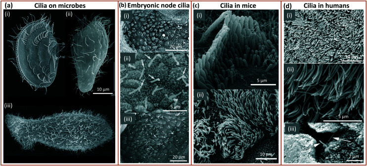
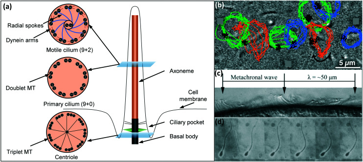
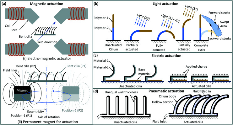
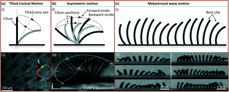
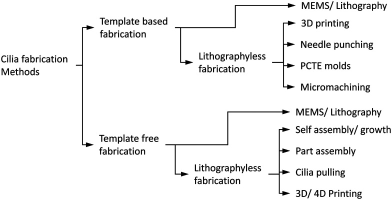
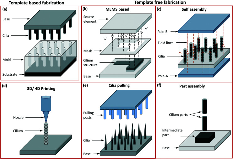
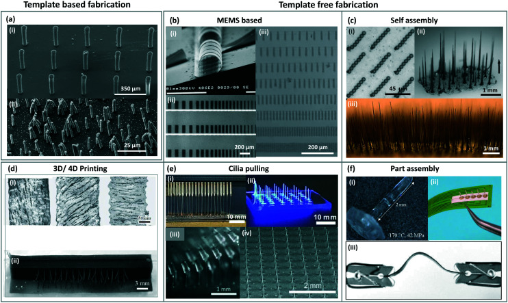
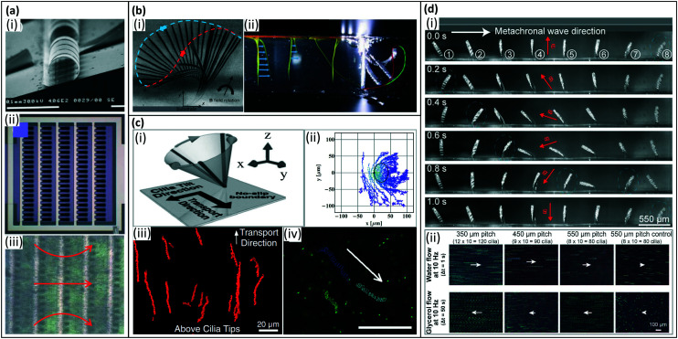
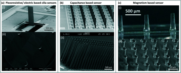
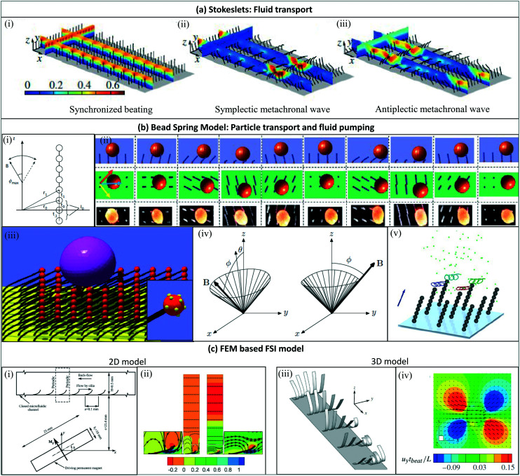
Cilia are microscopic hair-like external cell organelles that are ubiquitously present in nature, also within the human body. They fulfill crucial biological functions: motile cilia provide transportation of fluids and cells, and immotile cilia sense shear stress and concentrations of chemical species. Inspired by nature, scientists have developed artificial cilia mimicking the functions of biological cilia, aiming at application in microfluidic devices like lab-on-chip or organ-on-chip. By actuating the artificial cilia, for example by a magnetic field, an electric field, or pneumatics, microfluidic flow can be generated and particles can be transported. Other functions that have been explored are anti-biofouling and flow sensing. We provide a critical review of the progress in artificial cilia research and development as well as an evaluation of its future potential. We cover all aspects from fabrication approaches, actuation principles, artificial cilia functions - flow generation, particle transport and flow sensing - to applications. In addition to in-depth analyses of the current state of knowledge, we provide classifications of the different approaches and quantitative comparisons of the results obtained. We conclude that artificial cilia research is very much alive, with some concepts close to industrial implementation, and other developments just starting to open novel scientific opportunities.


Conflict of interest statement

There are no conflicts to declare.

Figures

Fig. 1
Fig. 1. Cilia in nature: (a) (i) ciliary pattern on the body of Leptopharynx costatus. Reproduced from ref. with permission from John Wiley and Sons. (ii) Cilia on the body of Platyophrya bromelicola. Reproduced from ref. with permission from Elsevier. (iii) Closely spaced cilia on Spathidium spathula. Reproduced from ref. with permission from Elsevier. (b) (i and ii) Cilia in the mouse embryonic node at an embryo age of 7.5 days. Reproduced from ref. and respectively with permission from Elsevier. (iii) Ciliated mouse embryonic node. Reproduced from ref. with permission from Springer Nature. (c) (i) Stereocilia staircase structure in mouse cochlear. Reproduced from ref. with permission from Springer Nature. (ii) Cilia on mouse tracheal epithelial cells. Reproduced from ref. with permission under open license CC BY. (d) (i) Human tracheal epithelial cilia. Reproduced from ref. with permission under open license CC BY. (ii) Cilia on human nasal epithelial cells. Reproduced from ref. with permission under open license CC BY. (iii) Sensing cilia in the renal tubule (kidney). Reproduced from ref. with permission from John Wiley and Sons.
Fig. 2
Fig. 2. (a) Schematic representation of the molecular structure of a cilium. The main components (basal body and axoneme) consist of microtubule (MT) doublets or triplets. For motile cilia, the axoneme possesses two central microtubules as well as upper and lower dynein arms. (b) Image showing a cilium performing a tilted conical motion along with the tracer lines of nodal cilia where the positions of the root are indicated in black, and the different tips in blue, green, and orange. Presence of cilia base/root close or on to the cilia tip trajectory indicate a tilted conical motion. Reproduced from the open access ref. . (c) Cilia on the epithelium of a flatworm (planarian) are shown here to display a metachronal motion, where individual cilia exhibit a whipping motion with consecutive cilia moving slightly out of phase. Reproduced from ref. with permission from the American Society for Cell Biology. (d) Wavy motion of a flagellum shown in a sequence of frames of a sperm cell performing wavy motion. Reproduced from ref. with permission from Elsevier.
Fig. 3
Fig. 3. Actuation principles of artificial cilia. (a) Magnetic actuation with (i) electromagnets and (ii) a moving permanent magnet; the cilia orientation follows the magnetic field direction. (b) Light driven motion of artificial cilia; two segments of the cilia body can be made to deflect under two different wavelengths of light irradiation, creating an asymmetrical motion with an appropriate sequence. (c) Electrostatic cilia can be made to deflect with an electric field, and they relax elastically when the field is removed; these cilia can be actuated relatively fast (up to hundreds of Hz). (d) Pneumatic or hydraulic actuation. Hollow, elastic cilia with asymmetric structures can be made to deflect and relax back when gas or liquid is pumped in a pulsating manner; when individually addressed, they can create a metachronal wave.
Fig. 4
Fig. 4. Artificial cilia motion types. (a) (i) Tilted conical motion; (ii) time-lapse image showing top-view of cilia under tilted conical motion, where the red arrow indicates the direction of effective stroke and the yellow arrow indicates the rotation direction. Reproduced from ref. with permission from John Wiley and Sons. (b) (i) 2D asymmetric motion with the swept area between the dotted lines representing forward and backward stroke; (ii) side-view image where the solid line indicates the effective stroke and the dashed line indicates the recovery stroke. Reproduced from ref. with permission from the Royal Society of Chemistry. (c) (i) Metachronal wave motion and (ii) time-sequence images from showing the wave propagation. Reproduced from ref. with permission under open license CC BY.
Fig. 5
Fig. 5. Flow chart showing the classification of the artificial cilia fabrication methods. The fabrication is broadly divided into template-based and template-free fabrication which is further divided into MEMS based (mostly involving lithography processes) and lithographyless fabrication methods. All the methods shown here are further represented in a tabular form in the ESI Table S1 along with the referred papers.
Fig. 6
Fig. 6. Schematic representation of different fabrication methods: (a) template-based fabrication where the mould is on the bottom side and the demoulded cilia on the top side with the base material made of either the same as cilia material or a different one. (b) The template free fabrication based on MEMS processes like thin film deposition, photolithography and etching, accompanied by other chemical treatment processes are used to mostly fabricate in-plane flap-shaped cilia structures. The source element shown here may either be a UV source or a source for metal coating etc. The mask may either be a separate unit or one deposited on the device surface itself. (c) The poles in the self assembly process are permanent or electro magnets used to align and assemble magnetic cilia structures, or can form an electric field aligning conducting material. (d) In 3D printing, the nozzle dispenses a material to form the cilia while, optionally (‘4D’), an external magnetic field imposes alignment of magnetic particles in the cilia during fabrication. (e) In cilia pulling, the pulling posts shown here may either be formed by solid structures (mostly PDMS) or by electrodes, which pull out hairlike structures from a liquid precursor film either by direct contact or by a localized electric field. (f) In part assembly, different units of the entire cilia structure are assembled to form a fully functional unit.
Fig. 7
Fig. 7. Images of artificial cilia made with different fabrication approaches. (a) SEM image of cilia (i) fabricated from a mould prepared from SU-8 using photolithography (MEMS) process. Reproduced from ref. with permission from Elsevier. (ii) shows cilia fabricated using PCTE as template/mould to shape a magnetic polymer into micro/nanoscale cilia structures. Reproduced from ref. with permission under open license CC BY-NC-ND. (b) SEM image of an actuable polymer cilia structure (i) fabricated using different MEMS process like vapour deposition, sputter coating, lithography etc. Reproduced from ref. with permission from the Royal Society of Chemistry. (ii) shows an array of rectangular shaped nickel–iron magnetic artificial cilia fabricated using two-mask lithography process. Reproduced from ref. with permission from the American Chemical Society. Magnetic artificial cilia of different sizes fabricated using a photolithographic process from a photoreactive copolymer are shown in (iii). Reproduced from ref. with permission from John Wiley and Sons. (c) Cilia in (i) are made from super-paramagnetic beads by self-aligning them using an external magnetic field. Reproduced from ref. with permission from Proceedings of the National Academy of Sciences. Cilia fabricated by aligning cobalt particles mixed with an elastomer by a magnet are shown in (ii). Reproduced from ref. with permission from the American Chemical Society. (iii) shows cilia fabricated by placing iron particles dispersed in a thermo-plastic polyurethane between two magnets to shape into the cilia structures. Reproduced from ref. with permission from John Wiley and Sons. (d) (i) shows the alignment of iron-carbonyl particles in different directions in the cilia structures fabricated using 4D printing process. Reproduced from the free access ref. . 3D printed cilia structures with each cilium having particles aligned in different directions is shown in (ii). Reproduced from ref. with permission under open license CC BY. (e) (i) and (ii) show cilia fabricated from a polymer by pulling them out of the plane using field effect spinning. Needles used to pull the cilia are shown in (i). Reproduced from ref. with permission from the American Chemical Society. PDMS posts (iii) on a roller used to pull a precursor material to shape them into cilia structures shown in (iv). Reproduced from ref. with permission from the Royal Society of Chemistry. (f) The cilium structure fabricated separately shown in (i) is one part of a complete unit. (ii) Shows cilia made from PMMA attached to the base through an epoxy resin to complete the device assembly. Reproduced from the open access ref. . A bistable buckled beam held between two clips that forms the cilium structure when attached to a fixed base is shown in (iii). Reproduced from ref. with permission from the Institute of Electrical and Electronics Engineers.
Fig. 8
Fig. 8. Artificial cilia used for fluid pumping. (a) Fluid flow generated by inertia effects of 2D reciprocal motion of electrostatic artificial cilia. (i) SEM image of the electrostatic artificial cilia; (ii) top view schematic of the layout of an array of electrostatic artificial cilia: the cilia are arranged in 5 columns of 20 cilia, and they are covered with a 0.5 mm thick film of silicone oil (viscosity 9.3 mPa s), containing TiO2 tracer particles; and (iii) snapshot of the flow generated by the electrostatic artificial cilia, the red arrows indicate the flow direction, the black dots are TiO2 tracer particles. Reproduced from ref. with permission from the Royal Society of Chemistry. (b) Fluid flow generated by 2D non-reciprocal motion. (i) Overlay of experimental images showing magnetic cilium motion over one beating cycle, the blue and red dashed lines indicate the cilium tip trajectory during the effective stroke and recovery stroke, respectively, which also demonstrate the difference in swept area by the cilium during the two strokes. Reproduced from ref. with permission from the Royal Society of Chemistry. (ii) Superimposed images of the dye tracing test of the initial situation and the situation after 130 beating cycles for 2D non-reciprocal motion of pneumatic artificial cilia, showing the generated net flow in the same direction as the effective stroke (indicated by the blue curve). Reproduced from ref. with permission from John Wiley and Sons. (c) Fluid flow generated by 3D non-reciprocal tilted conical motion. (i) Schematic of the cilia motion. Reproduced from ref. with permission from the National Academy of Sciences. (ii) Traces of particles above the cilium. The cilium is fixed at (0, 0) and the black solid line denotes the calculated path of the cilium tip. Reproduced from ref. with permission from the American Institute of Physics. (iii) Trajectory of tracer particles above the tips (z = 30 m), showing unidirectional flow. Reproduced from ref. with permission from the National Academy of Sciences. (iv) Traces of 1 μm fluorescent tracer particles in the horizontal plane, 40 mm above the bottom substrate, showing a net flow. The scale bar is 100 μm. Reproduced from ref. with permission from the Royal Society of Chemistry. (d) Fluid flow generated by 2D metachronal motion. (i) Snapshots of a metachronal motion of one row of MAC during one beating cycle at 1 Hz in water. (ii) Trajectories of tracer particles in both water and glycerol. The arrows indicate the relative speed and direction of the generated flow. Reproduced from ref. with permission under open license CC BY-NC-ND.
Fig. 9
Fig. 9. Summary of the net flow generated by previously reported artificial cilia listed in Table 1. (a) Absolute flow speed as a function of cilia length. The color of the symbols indicates cilia motion with purple, green and blue indicating 3D non-reciprocal motion, 2D non-reciprocal motion and 2D reciprocal motion, respectively. The circle and star symbols indicate whether the associated publication reports the local flow above the cilia tips or the global flow measured far away from the ciliated area, respectively. Solid filled data indicate the existence of a metachronal wave. (b) Normalized flow speed, δ = v/fl, as a function of cilia length (see Table 1 for the corresponding references). The symbols have the same meaning as in panel (a).
Fig. 10
Fig. 10. Fluid mixing with artificial cilia. (a) Fluid mixing with electrostatically actuated artificial cilia: (i) design of Y-shape microfluidic channel, (ii) optical image of the Y-shaped microfluidic device with two inlets for pumping in liquids and one outlet, (iii and iv) snapshots from a mixing experiment using dyed silicone oils; the mixing is complete within 1.5 cycles traveling distance in the main flow direction. Reproduced from ref. with permission from the Royal Society of Chemistry. (b) Fluid mixing with MAC: (i) design of T-shape microfluidic channel, (ii) and (iii) SEM image of the MAC, (iv and v) snapshots from a mixing experiment using glycerol aqueous dye solutions; the insert shows the trajectory made by the cilia tip. Reproduced with permission from Chen 2013. Reproduced from ref. with permission from the Royal Society of Chemistry.
Fig. 11
Fig. 11. Particle and droplet manipulation by artificial cilia. (a) Particle removal, self-cleaning and anti-biofouling by artificial cilia exhibiting tilted conical motion (upper left panel). Reproduced from ref. with permission from John Wiley and Sons. (a1) Use of magnetic artificial cilia to remove PLA particles in water. (i) SEM image of the MAC used in the article. (ii) shows the state of the surface before cleaning, (iii) is the state of the surface after actuating MAC for 60 s. (a2) Removal of natural sand grains by magnetic artificial cilia. (i)–(iii) show the cleaning process after 0 s 16 s and 30 s, respectively. a1 and a2 reproduced from ref. with permission from John Wiley and Sons. (a3) Anti-biofouling by magnetic artificial cilia. (i) Broader bright-field microscopy image of the ciliated part after 28 days actuation, showing that the central unciliated area is almost perfectly clean. (ii) Broader bright-field microscopy image of a control experiment after 28 days, showing that the complete channel is fouled indiscriminately. Reproduced from ref. with permission under open license CC BY-NC-ND. (b) Particle transport by artificial cilia exhibiting tilted conical motion (upperleft panel). (b1) Transport of ice particles by magnetically responsive film-like cilia. Because of the superhydrophobic wetting properties, ice particles form with nearly perfect spherical shapes. Reproduced from ref. with permission under open license CC BY. (b2) (i) Transporting droplets back and forth on a superhydrophobic magnetically responsive microplate array. (ii) Process of directional propulsion, merging, and mixing of water droplets on the surface. (iii) A simple chemical reaction based on the rapid droplet horizontal propulsion and microscopic positioning and merging. (iv) A water droplet (volume around 3 μL) climbing up an inclined superhydrophobic magnetically responsive microplate array surface at an inclination angle of around 5.4°. Reproduced from ref. with permission from the American Chemical Society. (b3) (i and ii) Morphology and corresponding water droplet contact angles of the magnetic microcilia before and after superhydrophobic modification, respectively. (iii) A water droplet can be switched between states of rolling down and pinning on an inclined surface by changing the magnetic field. (iv) Oil droplet manipulation in water on an inclined surface. Reproduced from ref. with permission under open license CC BY. (c) Particle control by artificial cilia exhibiting metachronal motion (lower middle panel). Reproduced from ref. and with permission from the American Chemical Society. (c1) (i) Magnetic artificial cilia with size of 50 μm in diameter, 350 μm in height. (ii) Top view of tilted conical motion shown by actuated cilia. (iii and iv) Top-view time-lapse trajectory of a particle transported along controlled directions. Reproduced from ref. with permission under open license CC-BY-NC-ND. (c2) Water droplet capture and on-demand release by a superhydrophobic magnetically responsive microplate array surface. Reproduced from ref. with permission from the American Chemical Society. (c3) (i) Water droplet moves reciprocally on a magnetic responsive cilia surface. (ii) Two droplets moving in parallel on a surface. (iii) Merging of droplets. (iv) Directional stable transportation of a droplet along a circular orbit. Reproduced from ref. with permission from the American Chemical Society.
Fig. 12
Fig. 12. Schematic representation of: (a) piezoresistive and piezoelectric cilia sensors where the cilium structure may be attached to one or multiple sensors/elements arranged either in its base or within the cilium structure. The sensors may experience deflection like represented by the bent configuration A and B depending on their type of arrangement around the cilium structure. (b) A capacitance based sensor integrated in the cilium base may be triggered by the bending of the cilium in the same manner as shown for the piezo sensors (configuration A and B). (c) A GMR or GMI sensor is placed under the cilia made from a magnetic material. Minute change in the magnetic field due to the deflection of magnetic cilia bought about by the surrounding fluid flow or vibrations is sensed by the sensor placed in the base.
Fig. 13
Fig. 13. Artificial cilia based sensors: (a) SEM image of a piezoresistive sensor based cilium with the piezoresistive element in the base (image-i) designed as per the configuration B shown in the schematic Fig. 12(a). Reproduced from ref. with permission from the Institute of Physics. In image-ii the sensing element is integrated within the cilium structure. Reproduced from ref. with permission from Elsevier. (b) SEM images of arras of cilia with a capacitive sensor integrated in the base both in image-i and ii, reproduced from ref. and respectively with permission from the Institute of Physics. (c) Magnetic artificial cilia containing magnetic nanowires embedded in PDMS (image-i) and SU-8 (image-ii) for measuring flow. Image-i reproduced from ref. with permission from the Royal Society of Chemistry. Image-ii reproduced from ref. with permission from the Institute of Electrical and Electronics Engineers.
Fig. 14
Fig. 14. Computational techniques utilized to resolve the fluid–cilia interaction. (a) The method of regularized Stokeslets is used to account for fluid transport: the shown velocity fields correspond to (i) synchronized cilia beating (ii) symplectic metachronal beating (iii) antiplectic metachronal beating. Reproduced from ref. with permission from Cambridge University Press. (b) The bead-spring model is widely used to study particle transport and fluid pumping applications. (i) A schematic representation of an artificial cilium by spherical beads connected through springs. Reproduced from ref. with permission from Springer Nature. (ii) The numerical results of particle transportation by magnetically actuated artificial cilia (top and side views first two rows) are compared with the experimental result (top view third row). Reproduced from ref. with permission under open license CC BY-NC-ND. (iii) A soft particle transported by adhesive cilia. Reproduced from ref. with permission from the American Chemical Society. (iv) The beating kinematics and pumping performance of a magnetically actuated artificial cilium. Reproduced from ref. with permission from Europhysics Letters. (v) The flow velocity generated by rotating artificial cilia. Reproduced from ref. with permission from the National Academy of Sciences. (c) Finite element based fully coupled 2D and 3D FSI solvers (i) a schematic of the problem in which magnetically actuated artificial cilia are used to generate the flow in a channel. (ii) The velocity fields are compared in the absence (left one) and in the presence of fluid inertia (right one). Image-i and ii are reproduced from ref. with permission from the Royal Society of Chemistry. (iii) metachronal beating of 3D plate-like cilia: the magnetically actuated thin plate or shell like artificial cilia immersed in a semi-infinite fluid for generating the flow. (iv) The velocity field generated by the in-phase beating of 3D cilia. Image-i and ii are reproduced from ref. with permission from Cambridge University Press.
None
Front row, from left to right: Ye Wang, Zhiwei Cui, Jaap M. J. den Toonder, Tanveer ul Islam, Tongsheng Wang, and Bhavana B. Venkataramanachar. Back row, from left to right: Hemanshul Garg, Hossein Eslami Amirabadi, Shuaizhong Zhang, Patrick R. Onck, Roel Kooi, and Ishu Aggarwal

References

    1. Sleigh M., Cilia and flagella, Academic Press, 1974
    1. Nonaka S. Shiratori H. Saijoh Y. Hamada H. Nature. 2002;418:96–99. doi: 10.1038/nature00849. - DOI - PubMed
    1. Singla V. Reiter J. Science. 2016;313:629–633. doi: 10.1126/science.1124534. - DOI - PubMed
    1. Praetorius H. Spring K. J. Membr. Biol. 2001;184:71–79. doi: 10.1007/s00232-001-0075-4. - DOI - PubMed
    1. Wilmer M. Ng C. Lanz H. Vulto P. Suter-Dick L. Masereeuw R. Trends Biotechnol. 2016;34:156–170. doi: 10.1016/j.tibtech.2015.11.001. - DOI - PubMed

Publication types