Review
. 2022 Apr 1;15(7):2601.
doi: 10.3390/ma15072601.

Magnetite Nanoparticles: Synthesis and Applications in Optics and Nanophotonics

Affiliations
Review

Magnetite Nanoparticles: Synthesis and Applications in Optics and Nanophotonics

Nataliia Dudchenko et al. Materials (Basel). .

Abstract

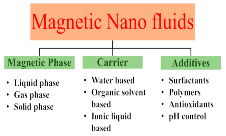
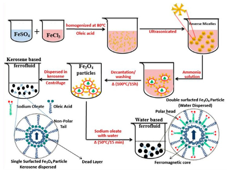
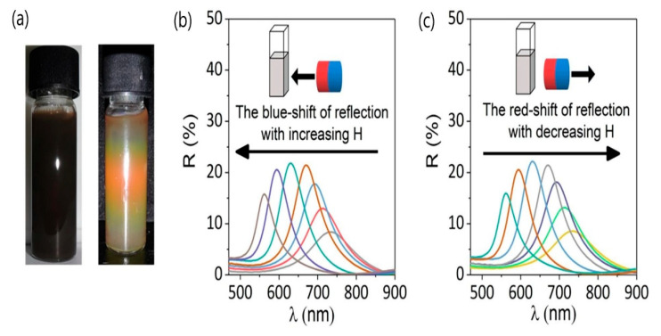
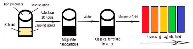
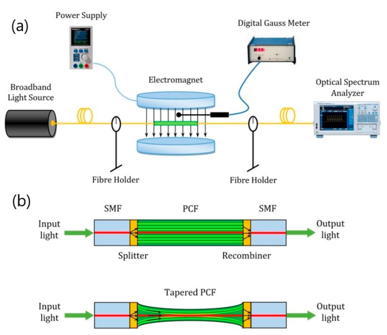
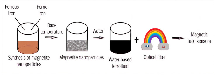
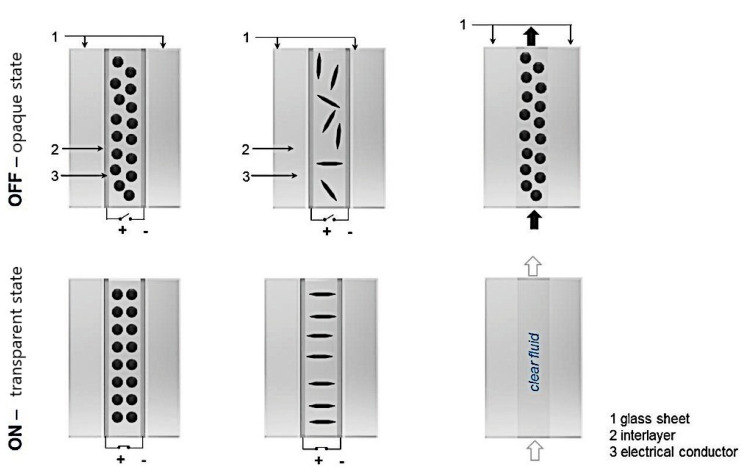
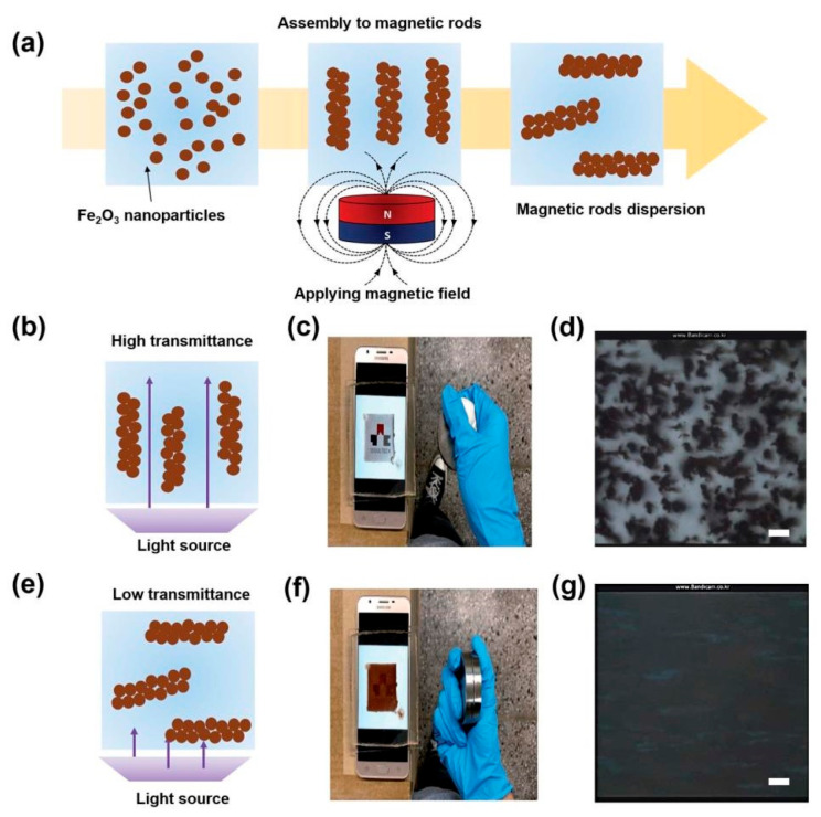
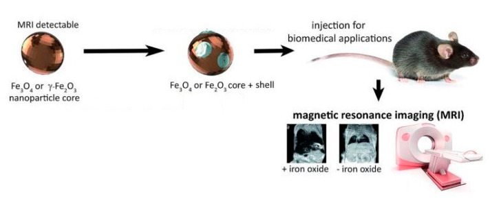
Magnetite nanoparticles with different surface coverages are of great interest for many applications due to their intrinsic magnetic properties, nanometer size, and definite surface morphology. Magnetite nanoparticles are widely used for different medical-biological applications while their usage in optics is not as widespread. In recent years, nanomagnetite suspensions, so-called magnetic ferrofluids, are applied in optics due to their magneto-optical properties. This review gives an overview of nanomagnetite synthesis and its properties. In addition, the preparation and application of magnetic nanofluids in optics, nanophotonics, and magnetic imaging are described.

Keywords: application; magnetic ferrofluids; magnetite nanoparticles; optical devices; synthesis.


Conflict of interest statement

The authors declare no conflict of interest.

Figures

Figure 1
Figure 1
Visualization of the magnetite unit cell identified using octahedral Fe2.5+ (dark grey), tetrahedral Fe2+ (light grey), and oxygen (red). The local site symmetries are shown by the octahedral and tetrahedral shapes around fully coordinated Fe sites within the unit cell. The different bond angles between the Fe sites lead to dominant antiferromagnetic coupling between the tetrahedral and octahedral sites, giving a bulk ferrimagnetic order (adapted from [34] with permission from Springer Nature).
Figure 2
Figure 2
Schematic representation of magnetite synthesis by co-precipitation method (adapted from [44] with permission from the Taylor & Francis Group).
Figure 3
Figure 3
Scanning Electron Microscopy (SEM) image of magnetite nanoparticles synthesized by co-precipitation method (adapted from [41] with permission from IOP Publishing).
Figure 4
Figure 4
High-resolution Transmission Electron Microscopy (TEM) images showing lattice fringes of the magnetite cores (adapted from [50] with permission from The Royal Society of Chemistry 2019).
Figure 5
Figure 5
SEM images of magnetite nanoparticles obtained after hydrothermal synthesis at different temperatures: (a,d) 120 °C, (b,e) 140 °C, and (c,f) 160 °C (adapted from [58] with permission from 2019 Nayely Torres-Gómez et al.).
Figure 6
Figure 6
TEM images of iron oxide nanoparticles synthesized using different reaction times in tri(ethylene glycol): (a) 1 h, (b) 2 h, (c) 4 h, (d) 8 h, (e) 12 h, and (f) 24 h (adapted from [63] with permission from the Royal Society of Chemistry).
Figure 7
Figure 7
Magnetite nanoparticle synthesis using plant extracts (adapted from [70] with permission from Elsevier).
Figure 8
Figure 8
TEM images of a single magnetotactic bacterium (a), of chains of magnetosomes extracted from whole magnetotactic bacteria (b), and of individual magnetosomes detached from the chains (c) (adapted from [74] with permission from 2014 Alphandéry).
Figure 9
Figure 9
Schematic representation of the preparation of magnetic nanofluids.
Figure 10
Figure 10
Schematic representation of the aqueous and kerosene-based magnetic fluid preparation by dispersing double surfactant (oleic acid (blue string) and sodium oleate (green string)) Fe3O4 MNPs using the two-step wet chemical synthesis method (adapted from [90] with permission from Elsevier, 2019).
Figure 11
Figure 11
Reversible optical responses of a 100 nm Fe3O4 colloid under increasing or decreasing external magnetic field (H): (a) digital photos of the Fe3O4 colloid without H (left) and with H (right); (b) blue shift in the reflection when H is enhanced; and (c) red shift in the reflection when H is weakened (adopted from [100] with permission from Elsevier, 2019).
Figure 12
Figure 12
Application of magnetic ferrofluids for the preparation of photonic materials.
Figure 13
Figure 13
Schematic diagram of (a) the experimental setup for magnetic feld sensing and (b) the in-line Mach–Zehnder interferometer in tapered photonic crystal fiber (PCF), with single mode fiber (SMF) (adapted from [108] with permission from the Springer Nature).
Figure 14
Figure 14
Application of magnetic ferrofluids for fabrication of magnetic field sensors.
Figure 15
Figure 15
Suspended particle device (SPD) technologies for switchable shading and control of optical transparency. An active fluid is contained within a glass–glass laminate in which an external trigger allows for variable orientation of (a) suspended particles or (b) liquid crystals. (c) A passive fluid with variable transparency flows through a microfluidic device (adapted from [111] with permission from John Wiley and Sons).
Figure 16
Figure 16
Schematic illustration of the formation of the magnetic microrods by applying a magnetic field (a). Schematic illustration of magnetic rods vertically oriented by controlling the magnetic field (b). Smart phone screen showing the university logo through the transparent cavity filled with magnetic rods (c). Microscopic image of the vertically oriented magnetic rods (d). Schematic illustration of magnetic rods oriented parallel to the surface by controlling the magnetic field (e). Smart phone screen showing the university logo through the transparent cavity filled with magnetic rods when the rods are in parallel to the surface (f). Microscopic image of the parallel oriented magnetic rods (g). The scale bars represent 100 μm (adapted from [112] with permission from the Royal Society of Chemistry).
Figure 17
Figure 17
Concept of iron oxide NP application in MR imaging (adopted from [113] with permission from the Royal Society of Chemistry).
Figure 18
Figure 18
T1-weighted MR images (B0 = 1 T) of mice collected before (control group) and after intravenous injection of Fe3O4-PAA at time points of 30, 60, 90, 120, 160, and 180 min (a). The corresponding relative T1-weighted signals extracted from (b) tumor (orange circle) and (c) kidney (dark yellow circle) sites (adapted from [118]).
Figure 19
Figure 19
The molecular structures of PTB7-F20 and PC71BM (a); the conventional device structure of PSCs without incorporating any Fe3O4 magnetic nanoparticles (MNPs) (b); the conventional device structure of PSCs incorporated with Fe3O4 MNPs and aligned by an external magnetostatic field (c); the fabrication procedures of PSCs incorporated with Fe3O4 MNPs and aligned by an external magnetostatic field (d)–(f); BHJ active layer incorporated with Fe3O4 MNPs was spin-coated on a PEDOT:PSS-coated ITO substrate (d); and a ferromagnet was suspend above the surface of BHJ composite incorporated with the Fe3O4 MNP layer. The magnetic intensity was ~30–40 G, and the distance between the ferromagnet and BHJ composite layer was ~10 cm (e); oriented Fe3O4 MNPs inside BHJ active layer by an external magnetostatic field. In pre-devices (f), a drawing of a partial enlargement of the Fe3O4 MNP in (c), showing an antiparallel relation between the magnetic dipole (caused by the Fe3O4 crystal inside the particle) and electric dipole (caused by the difference in charge density between the inside Fe3O4 and outside organic coater) (g) (adapted from [132] with permission from Scientific Reports).

References

    1. Piracha S., Saleem S., Momil G., Anjum A., Yaseen Z. Nanoparticle: Role in Chemical Industries, Potential Sources and Chemical Catalysis Applications. Sch. Int. J. Chem. Mater. Sci. 2020;4:40–45. doi: 10.36348/sijcms.2021.v04i04.006. - DOI
    1. Subhan A., Choudhury K.P., Neogi N. Advances with Molecular Nanomaterials in Industrial Manufacturing Applications. Int. J. Nanomanufacturing. 2021;1:75–97. doi: 10.3390/nanomanufacturing1020008. - DOI
    1. Pawar S., Duadi H., Fleger Y., Fixler D. Carbon Dots-Based Logic Gates. Nanomaterials. 2021;11:232. doi: 10.3390/nano11010232. - DOI - PMC - PubMed
    1. Prasad R., Bhattacharyya A., Nguyen Q.D. Nanotechnology in Sustainable Agriculture: Recent Developments, Challenges, and Perspectives. Front. Microbiol. 2017;8:124–127. doi: 10.3389/fmicb.2017.01014. - DOI - PMC - PubMed
    1. Usman M., Farooq M., Wakeel A., Nawaz A., Alam Cheema S.A., Rehman H.U., Ashraf I., Sanaullah M. Nanotechnology in agriculture: Current status, challenges and future opportunities. Sci. Total. Environ. 2020;721:137778. doi: 10.1016/j.scitotenv.2020.137778. - DOI - PubMed

LinkOut - more resources