Review
. 2022 Mar 31;22(7):2694.
doi: 10.3390/s22072694.

Advanced Fiber Sensors Based on the Vernier Effect

Affiliations
Review

Advanced Fiber Sensors Based on the Vernier Effect

Yunhao Chen et al. Sensors (Basel). .

Abstract

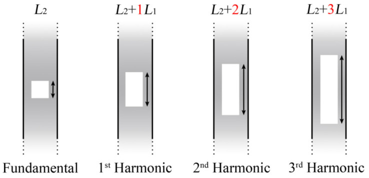
For decades, optical fiber interferometers have been extensively studied and applied for their inherent advantages. With the rapid development of science and technology, fiber sensors with higher detection sensitivity are needed on many occasions. As an effective way to improve measurement sensitivity, Vernier effect fiber sensors have drawn great attention during the last decade. Similar to the Vernier caliper, the optical Vernier effect uses one interferometer as a fixed part of the Vernier scale and the other as a sliding part of the Vernier scale. This paper first illustrates the principle of the optical Vernier effect, then different configurations used to produce the Vernier effect are classified and discussed. Finally, the outlook for Vernier effect fiber sensors is presented.

Keywords: Vernier effect; Vernier envelope; fiber sensor; magnification factor.


Conflict of interest statement

The authors declare no conflict of interest.

Figures

Figure 1
Figure 1
Vernier effect fiber sensor with two parallel connected FIs.
Figure 2
Figure 2
Working mechanism of the optical Vernier effect: (a) spectrum of the sensing and reference FI; (b) superimposed spectrum of the parallel connected FIs.
Figure 3
Figure 3
The relationship between the wavelength shift of the Vernier effect envelope and individual spectrum: (a) FSRr > FSRs, initial spectrum; (b) FSRr > FSRs, both the sensing spectrum and the Vernier envelope redshift; (c) FSRr < FSRs, initial spectrum; (d) FSRr < FSRs, sensing spectrum redshifts, the Vernier effect envelope blue shifts.
Figure 4
Figure 4
Configurations of Vernier effect fiber sensors based on FPIs: (a) in parallel [11]; (b) in series (physically connected); (c) in series (physically separated). Reprinted with permission from Ref. [11]. ©The Optical Society.
Figure 5
Figure 5
Vernier effect fiber sensor with: (a) cascaded MZIs; (b) parallel connected MZIs.
Figure 6
Figure 6
Experimental setup of the cascaded in-line MZIs [9]. Reprinted with permission from Ref. [9] ©The Optical Society.
Figure 7
Figure 7
Schematic diagrams of the Vernier effect fiber sensors based on paralleled MIs, (a) the sensor consists of an asymmetric dual-core fiber and a short section of DSHF [56], (b) the sensor consists of a pair of parallelized dual-core fiber MIs [57], (A) the sensor probe, (B) the schematic diagram of experimental system. Reprinted with permission from Ref. [56] ©Elsevier. Reprinted with permission from Ref. [57] ©The Optical Society.
Figure 8
Figure 8
Vernier effect fiber sensor formed by (a) cascading two FLMs [58], (b) inserting two Hi-Bi fiber segments into a fiber loop [62], (c) angle shift-splicing two Hi-Bi fibers in a single Sagnac loop [63]. Reprinted with permission from Refs. [58,63] ©Elsevier.
Figure 9
Figure 9
(a) Schematic diagram of the OMC. (b) Vernier effect operation principle of the OMC [66]. Reprinted with permission from Ref. [66] ©Elsevier.
Figure 10
Figure 10
Microfiber couplers connected in parallel to produce the Vernier effect [68]. Reprinted with permission from Ref. [68] ©The Optical Society.
Figure 11
Figure 11
Configuration of cascaded microfiber knot resonators [71]. Reprinted with permission from Ref. [71] ©The Optical Society.
Figure 12
Figure 12
Vernier effect fiber sensors based on hybrid configurations (MZI and FPI), (a) the FPI is fabricated by splicing a segment of HCF between SMFs, and the MZI is formed by two 3 dB couplers [72], (b) both the FPI and MZI were made up of core-offset structures [73]. Reprinted with permission from Ref. [72] ©Elsevier. Reprinted with permission from Ref. [73] ©The Optical Society.
Figure 13
Figure 13
Vernier effect fiber sensor based on hybrid configuration (SI and FPI) [74]. Reprinted with permission from Ref. [74] ©The Optical Society.
Figure 14
Figure 14
Vernier effect fiber sensor based on hybrid configuration (SI and MZI) [76]. Reprinted with permission from Ref. [76] ©Elsevier.
Figure 15
Figure 15
Schematic diagram of the relationship between the length of the reference interferometer (L2+iL1) and the sensing interferometer (L1), where i corresponds to the order of the harmonic [8].
Figure 16
Figure 16
Numerical simulations of the fundamental Vernier effect (a), and the first three harmonic orders (bd) [8]. Blue line: Simulations of the Vernier effect spectra. Dashed line: Upper envelope (shifted upward to be distinguishable from the internal ones). Red-orange lines: Internal envelopes.

References

    1. Miliou A. In-Fiber Interferometric-Based Sensors: Overview and Recent Advances. Photonics. 2021;8:265. doi: 10.3390/photonics8070265. - DOI
    1. Rao Y.J. Recent progress in fiber-optic extrinsic Fabry–Perot interferometric sensors. Opt. Fiber Technol. 2006;12:227–237. doi: 10.1016/j.yofte.2006.03.004. - DOI
    1. Zhao Y., Zhao H., Lv R.Q., Zhao J. Review of optical fiber Mach–Zehnder interferometers with micro-cavity fabricated by femtosecond laser and sensing applications. Opt. Lasers Eng. 2019;117:7–20. doi: 10.1016/j.optlaseng.2018.12.013. - DOI
    1. Culshaw B. The optical fibre Sagnac interferometer: An overview of its principles and applications. Meas. Sci. Technol. 2005;17:R1. doi: 10.1088/0957-0233/17/1/R01. - DOI
    1. Lee B.H., Kim Y.H., Park K.S., Eom J.B., Kim M.J., Rho B.S., Choi H.Y. Interferometric fiber optic sensors. Sensors. 2012;12:2467–2486. doi: 10.3390/s120302467. - DOI - PMC - PubMed

MeSH terms