. 2022 Jun 2;30(6):862-875.e4.
doi: 10.1016/j.str.2022.03.012. Epub 2022 Apr 11.

Structural basis for llama nanobody recognition and neutralization of HIV-1 at the CD4-binding site

Affiliations

Structural basis for llama nanobody recognition and neutralization of HIV-1 at the CD4-binding site

Tongqing Zhou et al. Structure. .

Abstract

Nanobodies can achieve remarkable neutralization of genetically diverse pathogens, including HIV-1. To gain insight into their recognition, we determined crystal structures of four llama nanobodies (J3, A12, C8, and D7), all of which targeted the CD4-binding site, in complex with the HIV-1 envelope (Env) gp120 core, and determined a cryoelectron microscopy (cryo-EM) structure of J3 with the Env trimer. Crystal and cryo-EM structures of J3 complexes revealed this nanobody to mimic binding to the prefusion-closed trimer for the primary site of CD4 recognition as well as a secondary quaternary site. In contrast, crystal structures of A12, C8, and D7 with gp120 revealed epitopes that included portions of the gp120 inner domain, inaccessible on the prefusion-closed trimer. Overall, these structures explain the broad and potent neutralization of J3 and limited neutralization of A12, C8, and D7, which utilized binding modes incompatible with the neutralization-targeted prefusion-closed conformation of Env.

Keywords: CD4-binding site; HIV; cryo-EM; crystal structure; envelope trimer; llama VHH; nanobody; neutralization; single-domain antibody; steric clash.


Conflict of interest statement

Declaration of interests The authors declare no competing interest.

Figures

Figure 1.
Figure 1.. Cryo-EM structure of J3 in complex with a Clade A-stabilized Env trimer reveals J3 to mimic CD4 binding to two adjacent protomers on the prefusion-closed trimer.
(A) Overall structure of the J3-BG505 DS-SOSIP complex. J3 is shown in cartoon representation colored green, and BG505 DS-SOSIP is shown as surface in shades of gray except for the J3-binding epitope, which is highlighted in forest-green. Glycans are shown in sticks. (B) J3 epitope highlighted in forest-green on the surface of Env trimer, in the same orientation as in (A) left panel. The epitope was defined as Env atoms within 5.5 Å of J3. Yellow outline indicates the footprint of CD4 mapped on the trimer surface of the J3 complex, by aligning the gp120 domain of the CD4-gp120 complex with that of the J3 complex. J3 binds across two adjacent protomers, slightly higher towards the trimer apex than CD4bs, but with substantial overlap and similar total contact surface area. (C) Superposition of the J3 complex with CD4 (PDB: 2NY1) and VRC01 (PDB: 5FYJ) complexes, by aligning the gp120 domain. Only the J3 complex, CD4 D1 domain, and VRC01 variable domains are shown for clarity. VRC01 is shown in marine blue for the heavy chain and slate blue for the light chain. CD4 is shown in yellow. See also Figure S2 and Table S2.
Figure 2.
Figure 2.. Cryo-EM structure of J3 with BG505 DS-SOSIP Env and crystal structure of J3 with clade C gp120 core exhibit identical J3 orientation with strong binding interactions to CD4bs residues.
(A) Alignment of the crystal structure of J3-C1086 gp120 core with the cryo-EM structure of J3-BG505 DS-SOSIP complex. The structural alignment was based on the Cα atoms of both gp120 and J3 residues. The cryo-EM structure is shown in green for J3 and gray for Env trimer. The gp120 core complex crystal structure is shown as orange round tubes with the diameter representing the pairwise Cα distances between the two structures. Cα distances greater than 10 Å and those unaligned residues are plotted as 10-Å diameter tubes to avoid obscuring the deviations of the aligned residues. The nanobodies aligned well; most of the gp120 core also aligned well, except residues 57-76 near trimer interface, residues flanking the deleted loops V1/V2 and V3 in the gp120 extended core construct, and residues at where either structure was disordered. (B) J3 paratope observed in the J3-BG505 DS-SOSIP Env complex. The paratope involved three CDRs to interact with the primary binding site and FR1, FR3, and N terminus with a secondary site on an adjacent protomer. There were some minor binding interactions between residues in FR3 and glycan197 in the primary site, and the secondary site binding involved glycan301. Nanobody residues involved in binding are highlighted in magenta. (C) Detailed binding interactions in the primary site. BG505 Env is shown as ribbon and transparent surface, with the epitope surface and atoms involved in binding highlighted in forest green. Nanobody side chains involved in binding are shown in sticks, with atoms within 5.5 Å of Env highlighted in magenta. Main chain carbonyl involved in hydrogen bonds are shown in sticks. Hydrogen bonds are shown as yellow dashed lines. H58J3 had a potential charge-charge interaction with D368gp120, shown as an orange dashed line, with a distance of ~4.0 Å. Y99J3 side chain bound in a hydrophobic cavity, with its OH group having a hydrogen bond to the side chain of D370gp120 at the bottom of the cavity. (D) Detailed binding interactions in the secondary site at the adjacent protomer. Quaternary interactions involved FR1, FR2, and N terminus of J3. Residues involved in the quaternary site binding are labeled. See also Figures S3–S5, and Tables S2–S4.
Figure 3.
Figure 3.. Crystal structure of A12 in complex with gp120 core reveals a binding site shifting toward the interface between protomers relative to the J3 epitope.
(A) Overall crystal structure of A12 in complex with gp120 coree from clade C in comparison with that of J3. HIV-1 gp120 is depicted in light gray semi-transparent surface with the nanobody epitopes colored forest green; nanobodies are depicted as ribbon diagrams with A12 colored marine-blue and J3 colored orange. The gp120 structures of both complexes are shown at the same viewing orientation, also the same orientation as the light-gray-colored gp120 subunit in Figure 1A left panel for easy comparison. The A12 binding site shifted away from the outer domain relative to that of J3. (B) Zoom-in view showing the detailed nanobody-gp120 interactions. The structures are shown in the same location and viewing angle, at a 45° rotation along the vertical axis relative to that in (A). Nanobody side chains involved in binding are shown in sticks, with atoms within 5.5 Å of Env highlighted in magenta. Similar to J3, the primary interactions for A12 were dominated by CDR3, with CDR1 providing additional contacts. The contact surface on gp120 for A12 shifted away from the outer domain. The bridging sheet was disordered in the A12 complexes, allowing the nanobody to bind to a portion of gp120 surface that was otherwise buried by the bridging sheet and part of gp120 absent in the gp120 coree construct, or blocked by the neighboring protomer in the Env trimer. See also Figure S3 and Table S3.
Figure 4.
Figure 4.. Crystal structures of C8 and D7 in complex with gp120 coree reveal a binding mode similar to that of A12, with a binding site shifting toward the interface between Env protomers.
(A) Overall crystal structures of C8 and D7 in complex with gp120 coree from clade B HxB2 and RHPA, respectively. In the two left panels, the gp120 structures are depicted as semi-transparent surface with the nanobody epitopes highlighted in forest-green; nanobodies are depicted as ribbon diagrams with C8 in slate-blue and D7 in cyan. The rightmost panel shows superposition of the two structures in ribbon diagram; gp120 is in dark gray for the C8 complex and light gray for the D7 complex. The structures are shown in the same viewing orientation as in Figure 3A for easy comparison. C8 and D7 bound at a site similar to that of A12, and shifted away from the outer domain relative to the J3 epitope. C8 interacted with some structural elements near apex that were disordered in the A12- and D7-gp120 complexes, and it bound at a slightly higher position than A12 and D7. (B) Zoom-in view at the epitope for the nanobody-gp120 detailed interactions. The structures are shown in the equivalent regions, viewed at a 45° rotation along the vertical axis relative to that in (A). The C8 and D7 epitopes are colored forest-green, with the footprint of J3 shown as green outline for comparison. Nanobody side chains involved in binding are shown in sticks, with atoms within 5.5 Å of Env highlighted in magenta. Hydrogen bonds are shown as yellow dashed lines. Similar to A12, the binding interactions for D7 were dominated by CDR3, with CDR1 providing additional contacts. However, C8 has a different set of paratope residues comprising CDR1, CDR2, CDR3, and FR3. The contact surface on gp120 for both nanobodies shifted away from the outer domain, and part of their contact surface on gp120 would be otherwise covered by the bridging sheet disordered in the crystal structures and by part of gp120 not present in the gp120 extended core construct, or blocked by the neighboring protomer in the Env trimer. See also Figure S3 and Table S3.
Figure 5.
Figure 5.. The binding mode of J3 in the gp120 core complex is compatible with binding to the prefusion-closed Env trimer, whereas A12, C8, and D7 have substantial clashes with Env trimer.
The nanobodies in crystal structures of gp120 coree complex, (A) J3-C1086, (B) A12-C1086, (C) C8-HxB2, and (D) D7-RHPA, were modeled onto the cryo-EM structure of J3-BG505 DS-SOSIP Env trimer by superposition of the gp120 domain using PyMOL. Env trimer surface around the binding site is shown with the gp120 of the primary binding site colored light gray and the adjacent protomer colored darker gray. The nanobody footprint on the trimer surface was defined as atoms within 5.5 Å of the nanobody and colored light teal; the trimer surface clashing with the modeled nanobody was defined as atoms within 2.0 Å of the nanobody and colored red. The J3 epitope as defined in the cryo-EM structure is shown as green contour for comparison.
Figure 6.
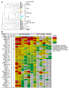
Figure 6.. Nanobodies A12, C8 and D7 neutralize mostly neutralization sensitive viruses, whereas J3 exhibits broad neutralization against both tier 1-neutralization sensitive and tier-2 neutralization resistant strains.
(A) Neutralization fingerprint analysis. (B) Neutralization IC50 of viruses neutralized by A12, C8 and D7. Nearly all viruses neutralized by D7 were also neutralized by A12 and C8. J3 had a different pattern of neutralization profile, and some viruses strongly neutralized by J3 were not neutralized by A12, C8, or D7. For comparison, neutralization data are also shown for soluble CD4 and human antibodies that preferentially recognize the open conformation of Env such as the CD4bs antibody F105, V3-antibodies 3074 and 447-52D, and CD4-induced antibodies 17b and 48d. See also Figures S1 and S7, and Table S1.

References

    1. Adams PD, Afonine PV, Bunkoczi G, Chen VB, Davis IW, Echols N, Headd JJ, Hung LW, Kapral GJ, Grosse-Kunstleve RW, et al. (2010). PHENIX: a comprehensive Python-based system for macromolecular structure solution. Acta Crystallogr D Biol Crystallogr 66, 213–221. - PMC - PubMed
    1. Adams PD, Gopal K, Grosse-Kunstleve RW, Hung LW, Ioerger TR, McCoy AJ, Moriarty NW, Pai RK, Read RJ, Romo TD, et al. (2004). Recent developments in the PHENIX software for automated crystallographic structure determination. J Synchrotron Radiat 11, 53–55. - PubMed
    1. Agarwal A, Hioe CE, Swetnam J, Zolla-Pazner S, and Cardozo T (2011). Quantitative assessment of masking of neutralization epitopes in HIV-1. Vaccine 29, 6736–6741. - PMC - PubMed
    1. Agirre J, Iglesias-Fernandez J, Rovira C, Davies GJ, Wilson KS, and Cowtan KD (2015). Privateer: software for the conformational validation of carbohydrate structures. Nat Struct Mol Biol 22, 833–834. - PubMed
    1. Barad BA, Echols N, Wang RY, Cheng Y, DiMaio F, Adams PD, and Fraser JS (2015). EMRinger: side chain-directed model and map validation for 3D cryo-electron microscopy. Nat Methods 12, 943–946. - PMC - PubMed

Publication types