. 2021 Jan 28;11(10):5384-5392.
doi: 10.1039/d1ra00110h.

Quality control of direct cell-mineral adhesion measurements in air and liquid using inverse AFM imaging

Affiliations

Quality control of direct cell-mineral adhesion measurements in air and liquid using inverse AFM imaging

Abd Alaziz Abu Quba et al. RSC Adv. .

Abstract

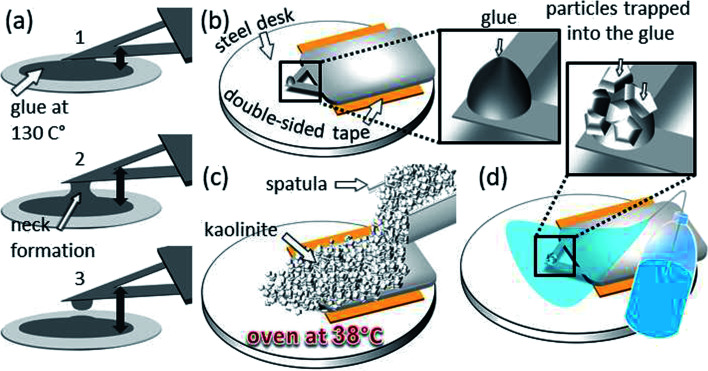
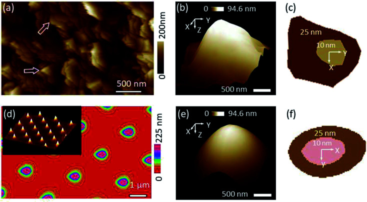
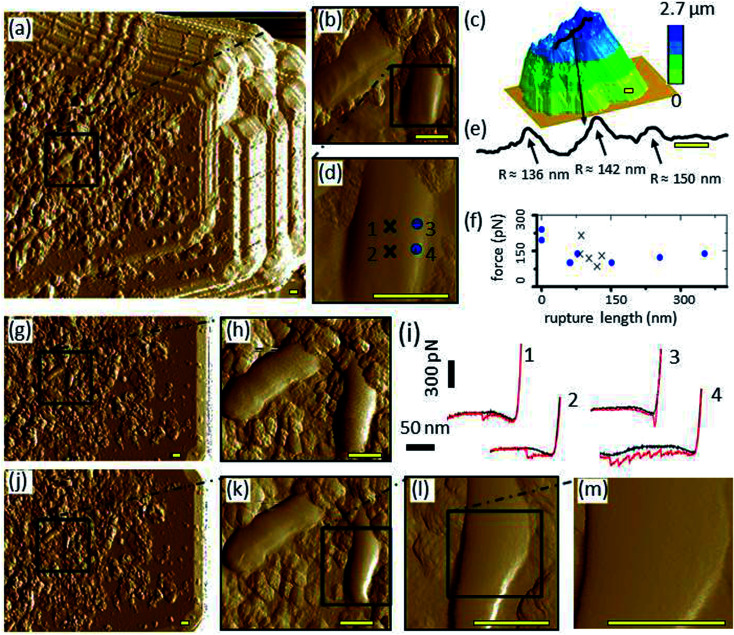
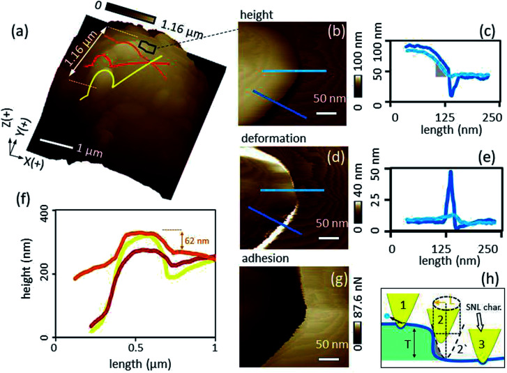
The study of interaction forces between biological and non-living systems requires in-house production of probes modified with, e.g., bacterial cells or with minerals, in order to map irregularly shaped natural surfaces. In order to avoid artifacts, it is essential to control the functionality of the modified probes. Current methods for this purpose require removing the modified probe from the liquid-cell, inserting it into another device and/or have a too low resolution to detect local changes within the interacting areas. Therefore, we present a fast and cost-effective method that overcomes the above mentioned problems by the inverse AFM imaging principle. First, the 3-D shape of a fresh sharp AFM tip is modeled by measuring the shape of a standard rough pattern and post blind tip reconstruction analysis. The so calibrated characterizer tip was extracted and upside-down fixed rigidly on a disc together with the sample. Before and after the cell-mineral interaction, the modified probe is then inversely imaged by the fixed characterizer controlling changes in finest 3-D details of the modified probe. The characterization of probes modified with kaolinite and P. fluorescens cells and their interactions with R. erythropolis and montmorillonite samples show that the method allows a fast precise investigation of tip modifications before and after cell-mineral interactions in air and liquid such that artifacts in adhesion between cell and mineral at the single-cell level can be excluded.


Conflict of interest statement

There are no conflicts of interest to declare.

Figures

Fig. 1
Fig. 1. Preparation steps for the kaolinite probe: (a) in the order from 1 to 3 a glue-tip formation by withdrawal process from the molten glue stain is demonstrated, (b) the substrate of the same probe glued to a double-sided adhesive tape onto a steel disc, (c) coverage of the whole probe with kaolinite particles using a spatula and post heating of the system at 38 °C for 30 minutes so the glue becomes more adhesive and (d) the probe and the tip after cleaning with Milli-Q water.
Fig. 2
Fig. 2. (a) Roughness image obtained by scanning a sharp SNL probe against titanium sample, (b) 3-D view of the tip that was blind tip reconstructed based on the rough pattern in (a), (c) 2-D sections of the tip at (b) at two Z levels (inner at Z = 10 nm and outer at Z = 25 nm starting from the tip apex as an origin), (d) roughness image obtained by scanning a Tap150A probe against TGT1 grating sample. The inset shows 3-D view of the TGT1 spikes, (e) and (f) are the same as (b) and (c) by analyzing (d) image. Using the grating yields better tip reconstruction in terms of the smoothness of the tip shape (e), however, leads to more elongated profile (f) compared to tip obtained at the titanium sample (b) and (c), respectively.
Fig. 3
Fig. 3. (a) Image of cell–mineral interactions between a bacteria (P. fluorescens) coated tip and a montmorillonite particle, (b) inset inside (a) of two bacteria cells, (d) inset inside (b), (c) height image of the respective montmorillonite particle made by a sharp probe in air, (e) line-scan as shown in (c), (i) cell–mineral FD curves at the locations indicated by the corresponding numbers in (d), (f) distribution of the minimum-adhesion-force-jump-magnitude in a relation to the rupture length of 45 FD curves from the cell center (x) and 30 FD curves from the cell edge (circles), (g) inverse image of the bacterial probe over the Tap150A characterizer before the cell–mineral interaction, with the inset (h) at the same location of (b), (j) inverse image with the insets (k and l) at the same locations of (b and d) after the cell–mineral interaction, (m) high resolution inset made to check the local structure of the investigated cell after the cell–mineral interaction. It is clear that the right-low edge of the cell (right cell in (h)) rearranges after the repetitive FD curves during the cell–mineral interaction as shown in (k and l). However, the cell center remains pure after the cell–mineral interaction (m) which indicates a valid adhesion experiments at the center. Scale bar 400 nm. If not stated otherwise, images were made in 10 mM KNO3 and images show the PeakForce error channel.
Fig. 4
Fig. 4. (a) 3-D view of the glue tip showing fine kaolinite clusters trapped at and around the tip apex, (b, d and g), inset from (a) showing height, deformation and adhesion channels, respectively, of an area at the kaolinite–glue interface, (c and e) sections of height, deformation channels, respectively, (f) Z extension of kaolinite cluster (yellow, red and orange lines in (a)) at the top of the glue, and (h) an imaginary series showing the influence of the kaolinite edge on the spatial resolution of the SNL characterizer (the dilation L is indicated by the golden arrow).
Fig. 5
Fig. 5. (a) Height image of cell–mineral interactions produced by scanning the kaolinite modified probe against a single R. erythropolis cell fixed at the AFM stage, (b) adhesion channel of the cell–mineral interaction addressed in (a), and (c) the respective R. erythropolis cell scanned by a sharp SNL probe. The finite details of the cell morphology in (c) appear triplicated in (a) which originates from the interaction between the kaolinite cluster at the top of the glue tip and the respective cell.

References

    1. Ma'shum M. Tate M. E. Jones G. P. Oades J. M. J. Soil Sci. 1988;39:99–110. doi: 10.1111/j.1365-2389.1988.tb01198.x. - DOI
    1. Doerr S. H. Shakesby R. A. Walsh R. P. D. Earth-Sci. Rev. 2000;51:33–65. doi: 10.1016/S0012-8252(00)00011-8. - DOI
    1. Miltner A. Bombach P. Schmidt-Brücken B. Kästner M. Biogeochemistry. 2012;111:41–55. doi: 10.1007/s10533-011-9658-z. - DOI
    1. Achtenhagen J. Goebel M.-O. Miltner A. Woche S. Kästner M. Biogeochemistry. 2015;122:269–280. doi: 10.1007/s10533-014-0040-9. - DOI
    1. Beaussart A. El-Kirat-Chatel S. Herman P. Alsteens D. Mahillon J. Hols P. Dufrêne Y. F. Biophys. J. 2013;104:1886–1892. doi: 10.1016/j.bpj.2013.03.046. - DOI - PMC - PubMed