. 2022 Apr 7;3(2):101279.
doi: 10.1016/j.xpro.2022.101279. eCollection 2022 Jun 17.

Protocol for inspecting blood cell dynamics with a custom ektacytometer-rheometer apparatus

Affiliations

Protocol for inspecting blood cell dynamics with a custom ektacytometer-rheometer apparatus

Tom Fitzpatrick et al. STAR Protoc. .

Abstract

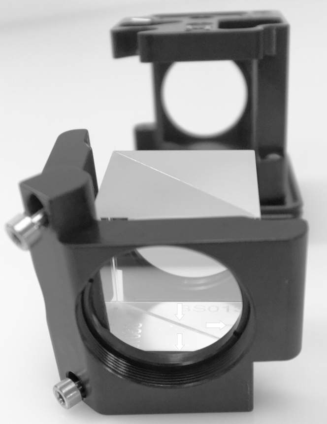
Investigating flowing red blood cell (RBC) morphology and orientation is important for elucidating physiology and disease; existing commercially available products are limited to observing cell populations or single cells. In this protocol, we create a custom apparatus that combines coaxial brightfield microscopy with laser diffractometry to inspect near-real-time deformability, morphology, and orientation of flowing RBCs. There are difficulties associated with building optical systems for biological inspection; however, this protocol provides a suitable framework for developing an "ektacytoscope" for studying blood cells. For complete details on the use and execution of this protocol, please refer to McNamee et al. (2020).

Keywords: Biophysics; Biotechnology and bioengineering; Cell Biology; Cell Membrane; Microscopy; Physics; Systems biology.


Conflict of interest statement

The authors declare no competing interests.

Figures

None
Graphical abstract
Figure 1
Figure 1
The assembled optical system for combined ektacytometry and rheometry (A–J) Functional subsections of the assembly are labeled: Brightfield illumination arm (A), Laser illumination arm (B), Central arm and sample stage (C), Diffraction imaging arm (D), Brightfield imaging arm (E), Beam splitter cube holders (F and G), Syringe pump, sample syringe, and shear chamber inlet tube (H), Shear chamber (I), Waste receptacle and shear chamber outlet tube (J).
Figure 2
Figure 2
Detail of the brightfield illumination arm with sub-component assemblies (A–G) Field stop diaphragm (A), Relay lens (B), Aperture stop diaphragm (C), Second collector lens (D), First collector lens (E), Broadband light source diaphragm (F), Broadband light source (G). (Note: slight variations exist between the figure and instructions for parts A, E, and G. See the included CAD model for an updated assembly reference).
Figure 3
Figure 3
Detail of the laser illumination arm with sub-component assemblies (A and B) Laser mount (A), ND filter holder post (B).
Figure 4
Figure 4
Detail of the central arm and sample stage with sub-component assemblies (A–C) Condenser lens (A), Objective lens holder (B), XY slit flow chamber stage holder (C). (Note: the XY slit flow chamber stage holder and linear stage in the image is no longer commercially available. While a different stage holder could be manufactured/printed, to maximize accessibility alternate components that are currently commercially available are listed in the work instructions andkey resources table. See the included CAD model for an updated assembly reference).
Figure 5
Figure 5
Detail of the diffraction imaging arm with sub-component assemblies (A and B) Diffraction imaging camera assembly (A) and Diffraction camera tube lens (B).
Figure 6
Figure 6
Detail of the brightfield imaging arm with sub-component assemblies (A) Brightfield imaging camera assembly (A).
Figure 7
Figure 7
Detail of the beam splitter cube holders with sub-component assemblies (A and B) Beam splitter cube holder A (A), and Beam splitter cube holder B (B).
Figure 8
Figure 8
Beam splitter cube alignment Detail of beam splitter cube alignment for cube holder A showing correct orientation with the corner of the cube tangent to the inner beam splitter coating with a single arrow (not two arrows) towards the captive bolts.
Figure 9
Figure 9
Beam splitter cube alignment Detail of beam splitter cube alignment for cube holder A showing correct orientation with the corner in line to the inner beam splitter coating with a single arrow next to and pointing away from the captive bolts. The corner with two arrows is on the opposite side and pointing away from the captive bolts.
Figure 10
Figure 10
Slit flow shear chamber secured and positioned in the sample stage holder assembly Note: Objective lens assembly retracted out of the way for picture.
Figure 11
Figure 11
Detail of the laser illumination arm with added alignment components (A–C) ND filter with optical density of 1.0 (A), cage alignment plate (B), two 6″ ER cage rods (C).
Figure 12
Figure 12
Example image analysis processing of representative images collected from the laser diffraction acquisition camera for a RBC-PVP suspension sheared at 0.3 and 10 Pa
Figure 13
Figure 13
Example image analysis processing of representative images collected from the brightfield illumination acquisition camera for a RBC-PVP suspension sheared at 0.3 and 10 Pa
Figure 14
Figure 14
Example processed data acquired from the combined ektacytometer-rheometer optical system for a healthy RBC-PVP sample sheared between 0.3 and 10 Pa (A–D) RBC deformability (EI) curves are displayed for concurrently acquired laser diffraction data (A) and captured brightfield visualization images (C). The stability of RBC in a constant 10 Pa shear flow and subsequent shape recovery is presented (B). The orientation angle of RBC (relative to a C=0 orbit) is displayed for 10° groups for the entire RBC population assessed within each shear condition (D).

References

    1. Bartoli V., Albanese B., Manescalchi P.G., Mannini L., Pasquini G. Influence of blood storage conditions and anticoagulants on results of blood cell filtration test. Clin. Hemorheol. Microcirc. 1986;6:137–149.
    1. Baskurt O.K., Boynard M., Cokelet G.C., Connes P., Cooke B.M., Forconi S., Liao F., Hardeman M.R., Jung F., Meiselman H.J., et al. New guidelines for hemorheological laboratory techniques. Clin. Hemorheol. Microcirc. 2009;42:75–97. - PubMed
    1. Baskurt O.K., Hardeman M.R., Uyuklu M., Ulker P., Cengiz M., Nemeth N., Shin S., Alexy T., Meiselman H.J. Parameterization of red blood cell elongation index–shear stress curves obtained by ektacytometry. Scand. J. Clin. Lab. Invest. 2009;69:777–788. - PubMed
    1. Edmund Optics Inc Cleaning optics. 2022. https://www.edmundoptics.com.au/knowledge-center/application-notes/optic...
    1. McNamee A.P., Fitzpatrick T., Tansley G.D., Simmonds M.J. Sublethal supraphysiological shear stress alters erythrocyte dynamics in subsequent low-shear flows. Biophys. J. 2020;119:2179–2189. - PMC - PubMed

Publication types

LinkOut - more resources