Effect of the Incorporation of ZIF-8@GO into the Thin-Film Membrane on Salt Rejection and BSA Fouling
- PMID: 35448406
- PMCID: PMC9027943
- DOI: 10.3390/membranes12040436
Effect of the Incorporation of ZIF-8@GO into the Thin-Film Membrane on Salt Rejection and BSA Fouling
Abstract
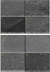
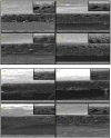
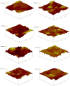
A series of Zeolitic imidazole framework-8 (ZIF-8) clusters supported on graphene oxide (ZIF-8@GO) nanocomposites were prepared by varying the ratios of ZIF-8 to GO. The resultant nanocomposites were characterized using various techniques, such as Scanning Electron Microscope (SEM), Transmission Electron Microscope (TEM), X-ray diffraction (XRD), Brunauer-Emmett-Teller (BET), thermogravimetric analysis (TGA), Fourier Transform Infrared (FTIR) and Raman spectroscopy. These nanocomposites were incorporated into the thin film layer during interfacial polymerisation process of m-phenylenediamine (aqueous phase which contained the dispersed nanocomposites) and trimesoyl chloride (TMC, organic phase) at room temperature onto polyethersulfone (PES) ultrafiltration (UF) support membrane. The membrane surface morphology, cross section and surface roughness were characterized using SEM and AFM, respectively. Compared to the baseline membranes, the thin film nanofiltration (TFN) membranes exhibited improved pure water flux (from 1.66 up to 7.9 L.m-2h-1), salt rejection (from 40 to 98%) and fouling resistance (33 to 88%). Optimum ZIF-8 to GO ratio was established as indicated in observed pure water flux, salt rejection and BSA fouling resistance. Therefore, a balance in hydrophilic and porous effect of the filler was observed to lead to this observed membrane behaviour suggesting that careful filler design can result in performance gain for thin film composite (TFC) membranes for water treatment application.
Keywords: graphene oxide; interfacial polymerization; nanofiltration; thin film composite membranes; zeolitic imidazole framework-8.
Conflict of interest statement
The authors declare no conflict of interest.
Figures


References
-
- Arumugham T., Kaleekkal N.J., Rana D. Fabrication of novel aromatic amine functionalized nanofiltration (NF) membranes and testing its dye removal and desalting ability. Polym. Test. 2018;72:1–10. doi: 10.1016/j.polymertesting.2018.09.028. - DOI
-
- Carolin C.F., Kumar P.S., Saravanan A., Joshiba G.J., Naushad M. Efficient techniques for the removal of toxic heavy metals from aquatic environment: A review. J. Environ. Chem. Eng. 2017;5:2782–2799. doi: 10.1016/j.jece.2017.05.029. - DOI
-
- Yu C., Lia H., Zhanga X., Lüa Z., Yua S., Liub M., Gao C. Polyamide thin-film composite membrane fabricated through interfacial polymerization coupled with surface amidation for improved reverse osmosis performance. J. Membr. Sci. 2018;566:87–95. doi: 10.1016/j.memsci.2018.09.012. - DOI
-
- Baker R.W. Future directions of membrane gas separation technology. Ind. Eng. Chem. Res. 2002;41:1393–1411. doi: 10.1021/ie0108088. - DOI
Grants and funding
LinkOut - more resources
Full Text Sources
Miscellaneous

