. 2022 Apr 11;15(8):2801.
doi: 10.3390/ma15082801.

3D-Printed Double-Helical Biodegradable Iron Suture Anchor: A Rabbit Rotator Cuff Tear Model

Affiliations

3D-Printed Double-Helical Biodegradable Iron Suture Anchor: A Rabbit Rotator Cuff Tear Model

Wen-Chih Liu et al. Materials (Basel). .

Erratum in

Abstract

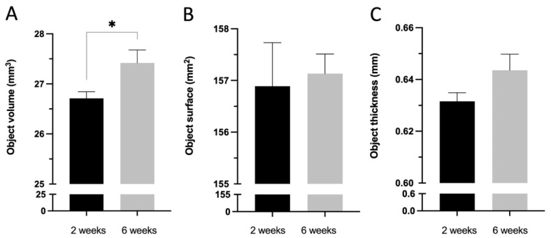
Suture anchors are extensively used in rotator cuff tear surgery. With the advancement of three-dimensional printing technology, biodegradable metal has been developed for orthopedic applications. This study adopted three-dimensional-printed biodegradable Fe suture anchors with double-helical threads and commercialized non-vented screw-type Ti suture anchors with a tapered tip in the experimental and control groups, respectively. The in vitro study showed that the Fe and Ti suture anchors exhibited a similar ultimate failure load in 20-pound-per-cubic-foot polyurethane foam blocks and rabbit bone. In static immersion tests, the corrosion rate of Fe suture anchors was 0.049 ± 0.002 mm/year. The in vivo study was performed on New Zealand white rabbits and SAs were employed to reattach the ruptured supraspinatus tendon. The in vivo ultimate failure load of the Fe suture anchors was superior to that of the Ti suture anchors at 6 weeks. Micro-computed tomography showed that the bone volume fraction and bone surface density in the Fe suture anchors group 2 and 6 weeks after surgery were superior, and the histology confirmed that the increased bone volume around the anchor was attributable to mineralized osteocytes. The three-dimensional-printed Fe suture anchors outperformed the currently used Ti suture anchors.

Keywords: 3D printing; biodegradable metal; iron; rabbit; rotator cuff; suture anchor.


Conflict of interest statement

The funders had no role in the design of the study; in the collection, analysis, or interpretation of data; in the writing of the manuscript; or in the decision to publish the results.

Figures

Figure 1
Figure 1
Specifications of the (A) open-construct double-helical Fe suture anchor (SA) and (B) screw-type Ti SA. (C) Illustration of the open-construct double-helical Fe SA.
Figure 2
Figure 2
(A) The dimensions of the Fe SA were 11.0 × 3.5 mm. (B) An inserter handle was designed to hold the Fe SA, which was inserted into a predrilled hole on the polyurethane foam block. (C) After inserting the SA and removing the inserter handle, the suture exited the core of the iron SA. (D) The control group: the non-vented screw-type Ti SA had a tapered tip portion with sutures through the proximal eyelet. The suture was passed through the eyelet at the top of the SA. The Ti SA was pulled out of the polyurethane foam block during the mechanical test.
Figure 3
Figure 3
(A) The SST of the rabbit was identified. (B) The SST was sharply dissected with a scalpel blade and (C) the SST was detached from the insertion of the humerus. (D) A drill bit was used to predrill a hole in the humerus insertion of the SST. (E) After inserting the SA, the two ends of the suture exited from the SST insertion. (F) The SST was repositioned to the footprint using a modified Mason–Allen stitch.
Figure 4
Figure 4
The radiograph shows that the Ti SA (left shoulder) and Fe SA (right shoulder) were inserted into the proximal humerus greater tuberosity.
Figure 5
Figure 5
The reconstructed cross-sections were re-orientated, and the region of interest (ROI) was further selected. The 3.5 mm implant column was isolated. (A) The analysis was performed with 3 mm images (100 slices, 3–6 mm from the end of the implant). Automatic Ostu thresholding and bone ingrowth analysis were performed using CTAn software. (B) The ROI was defined as a 200–1000 μm region around the implant.
Figure 6
Figure 6
In vitro biomechanical ultimate pullout strength assessment for the different SAs in 20-pound-per-cubic-foot (pcf) polyurethane foam blocks and rabbit humeri. Mean ± standard error of the mean (SEM).
Figure 7
Figure 7
In vitro corrosion characteristics of the Fe SA. Mean ± SEM.
Figure 8
Figure 8
In vivo biomechanical ultimate pullout strength assessment for different SAs at 0, 2, and 6 weeks after surgery. Mean ± SEM. * p < 0.05.
Figure 9
Figure 9
Three different modes of failure after the ultimate pullout strength assessment. (A) Failure at the tendon–suture junction (arrow). (B) Failure at the suture–anchor junction. That is, the end of the suture ruptured from the anchor (arrowhead). (C) The SA was pulled out. T, tendon; S, suture; A, anchor.
Figure 10
Figure 10
Micro-computed tomography (micro-CT) analysis. Quantitative evaluation of the bone volume (BV) between the bone and SAs. The tissue volume (TV, mm3), BV (mm3), and BS (mm2) were examined in a region of interest (ROI) of 200–1000 μm around the implant. (A) BV fraction (BV/TV, %) and (B) BS density (BS/TV, mm−1) represent the BV rate and bone tissue surface rate, respectively. Mean ± SEM. * p < 0.05.
Figure 11
Figure 11
Micro-CT analysis. (A) Titanium SA 2 weeks after implantation. The BV fraction was 27.77% and the bone surface (BS) density was 4.52 mm−1. (B) Iron SA 2 weeks after implantation. The BV fraction was 38.20% and the BS density was 6.05 mm−1.
Figure 12
Figure 12
Micro-CT analysis. (A) Ti SA 6 weeks after implantation. The BV fraction was 29.59% and the BS density was 4.57 mm−1. (B) Fe SA 6 weeks after implantation. The BV fraction was 39.78% and the BS density was 6.31 mm−1.
Figure 13
Figure 13
Micro-CT degradation analysis of the Fe SA groups 2 and 6 weeks postoperation in (A) Objective volume (mm2), (B) Object surface (mm2), and (C) Object thickness (mm). Mean ± SEM. * p < 0.05.
Figure 14
Figure 14
Reconstructed micro-CT images of two Fe SAs (A) 2 weeks postoperation and (B) 6 weeks postoperation.
Figure 15
Figure 15
Micro-CT and histological examination of the bone–SA interface 2 and 6 weeks postoperation. w, week; A, anchor; S, suture; DP, degradation products; MO, mineralized osteocytes.
Figure 16
Figure 16
(A) Level of serum blood urea nitrogen (BUN; mg/dL), (B) level of serum alanine transaminase (ALT; U/L), (C) level of serum albumin (Alb; g/dL), and (D) level of creatinine (Cr; mg/dL) preoperation and 2 and 6 weeks postoperation. Mean ± SEM.

References

    1. Tashjian R.Z. Epidemiology, natural history, and indications for treatment of rotator cuff tears. Clin. Sports Med. 2012;31:589–604. doi: 10.1016/j.csm.2012.07.001. - DOI - PubMed
    1. Kim J.H., Kim Y.S., Park I., Lee H.J., Han S.Y., Jung S., Shin S.J. A Comparison of open-construct PEEK suture anchor and non-vented biocomposite suture anchor in arthroscopic rotator cuff repair: A prospective randomized clinical trial. Arthroscopy. 2020;36:389–396. doi: 10.1016/j.arthro.2019.08.049. - DOI - PubMed
    1. Longo U.G., Petrillo S., Loppini M., Candela V., Rizzello G., Maffulli N., Denaro V. Metallic versus biodegradable suture anchors for rotator cuff repair: A case control study. BMC Musculoskelet. Disord. 2019;20:477. doi: 10.1186/s12891-019-2834-3. - DOI - PMC - PubMed
    1. Suchenski M., McCarthy M.B., Chowaniec D., Hansen D., McKinnon W., Apostolakos J., Arciero R., Mazzocca A.D. Material properties and composition of soft-tissue fixation. Arthroscopy. 2010;26:821–831. doi: 10.1016/j.arthro.2009.12.026. - DOI - PubMed
    1. Stoetzel S., Malhan D., Wild U., Helbing C., Hassan F., Attia S., Jandt K.D., Heiss C., El Khassawna T. Osteocytes influence on bone matrix integrity affects biomechanical competence at bone-implant interface of bioactive-coated titanium implants in rat tibiae. Int. J. Mol. Sci. 2021;23:374. doi: 10.3390/ijms23010374. - DOI - PMC - PubMed

LinkOut - more resources