

3D Printing Application in Wood Furniture Components Assembling
- PMID: 35454600
- PMCID: PMC9031870
- DOI: 10.3390/ma15082907
3D Printing Application in Wood Furniture Components Assembling
Abstract
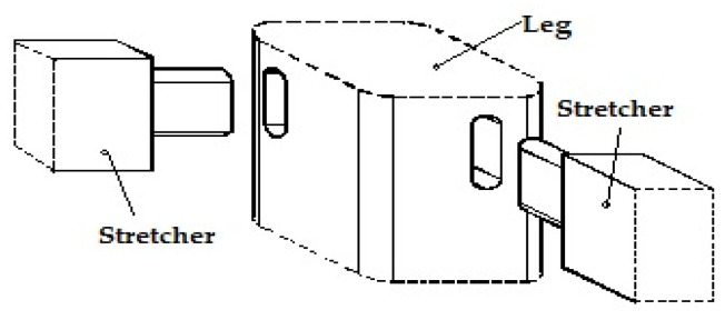
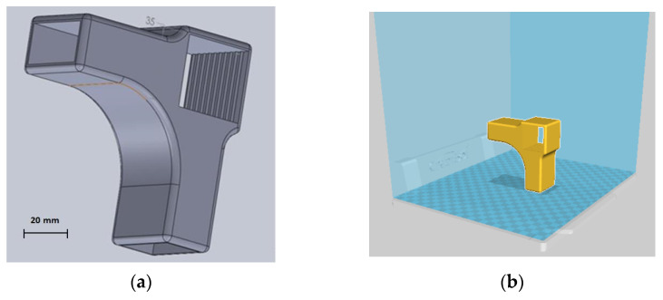
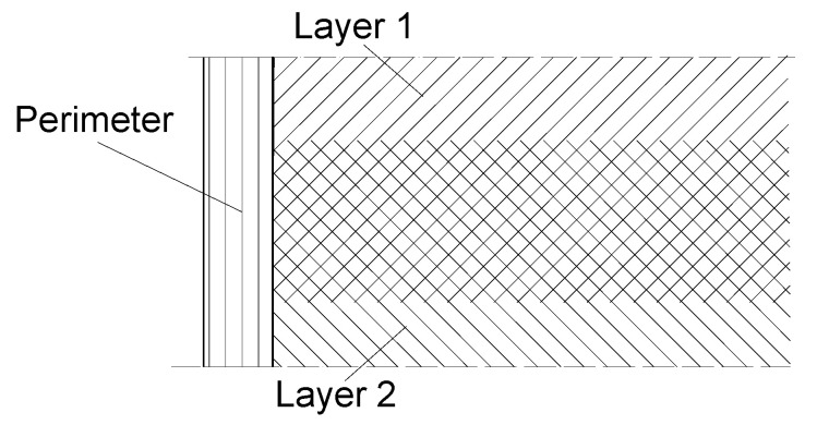
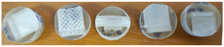
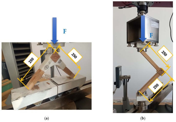
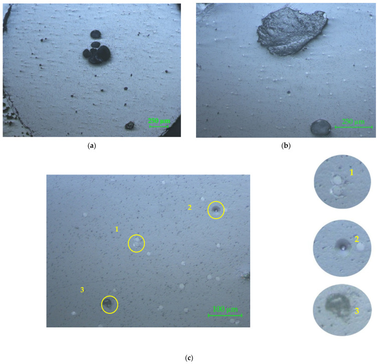
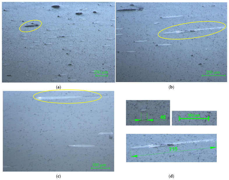
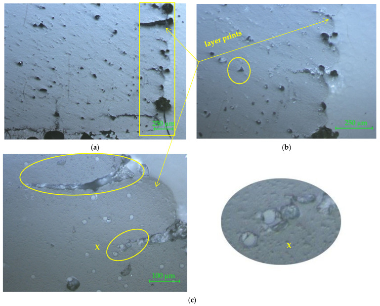
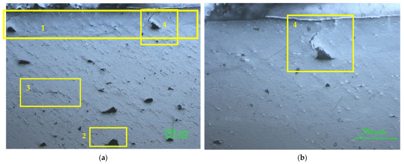
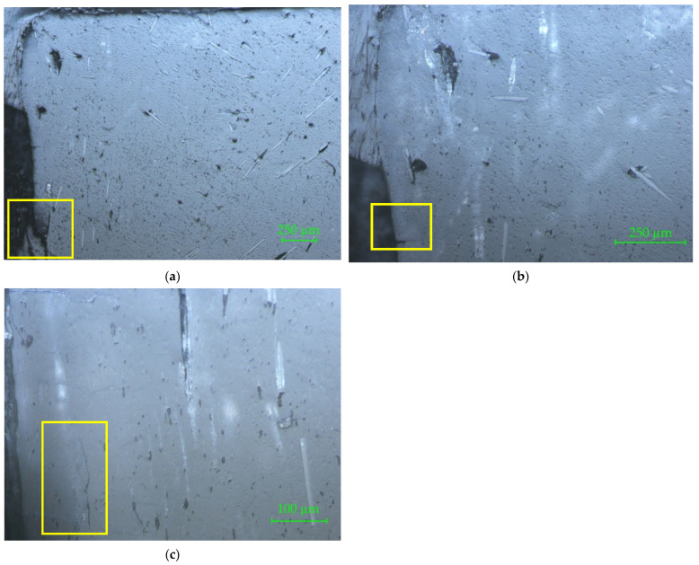
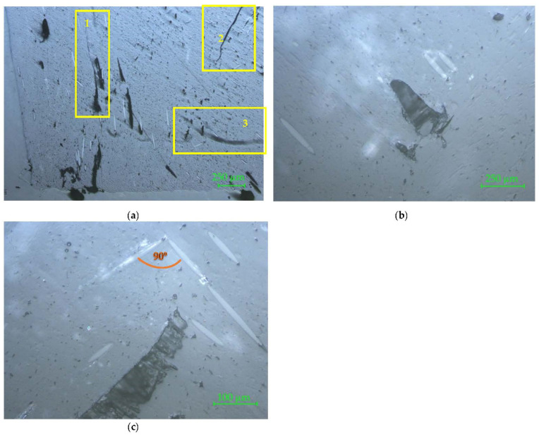
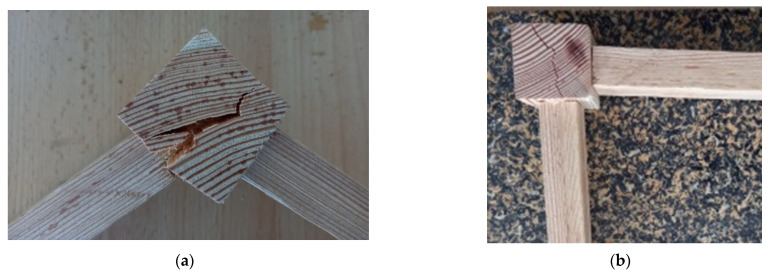
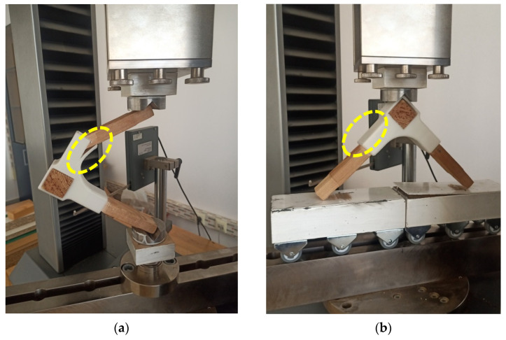
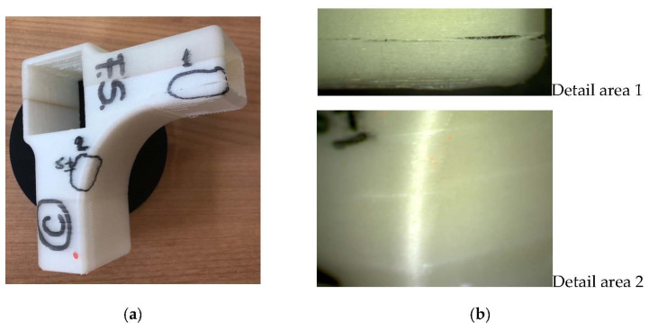
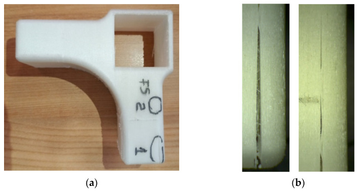
Additive manufacturing (AM) is used in many fields and is a method used to replace wood components or wood-jointed furniture components in the furniture industry. Replacing wood joints by 3D printed connectors would be an advantage, considering the fact that during the process of assembling furniture, the execution technology of the joints is difficult, time-consuming, and labor-intensive. Advanced technology of AM applied in furniture manufacturing helps the designers to create new concepts of product design, with no limits of shape, number of joints, color, or size. The diversity of 3D printers and AM technologies provides the selection of materials in relation with the applicability of the 3D printed object. In this respect, the objective of the present research is to design a 3D printed connector to be used for jointing three chair components, namely the leg and two stretchers made from larch (Larix decidua Mill.) wood, and to use reinforced polylactic acid (PLA) fiberglass (20 wt. %) filament for 3D printing this connector using AM with fused filament fabrication (FFF) technology. The design of the connector, the possibility of using this type of material, and the deposition method of filament were investigated in this research. For this purpose, several evaluation methods were applied: microscopic investigation with 50×, 100×, and 200× magnifications, both of the filament and of the 3D printed connector; mechanical testing of corner joint formed with the help of connector between chair leg and the two stretchers; and a microscopic investigation of the connectors' defects that occurred after applying the compression and tensile loads on the diagonal direction of the L-type joint. The microscopic investigation of the composite filament revealed the agglomerations of glass fibers into the core matrix and areas where the distribution of the reinforcements was poor. The heterogeneous structure of the filament and the defects highlighted in the 3D printed connectors by the microscopic investigation contributed to the mechanical behavior of L-type connecting joints. The bending moments resulting from compression and tensile tests of the 3D printed connectors were compared to the results recorded after testing, under the same conditions, the normal mortise-tenon joint used to assemble the abovementioned chair components. The larch wood strength influenced the mechanical results and the conclusions of the microscopic investigations, as well as the analysis of the broken connectors after testing recommended the change of connector design and filament deposition direction.
Keywords: 3D printed connector; additive manufacturing; mortise–tenon joint; polylactic acid (PLA); wood furniture.
Conflict of interest statement
The authors declare no conflict of interest.
Figures
References
-
- Valiyousefi M., Alihedarloo A. A Study the impact of 3D-printed joints on the complex wooden structures; Proceedings of the International congress on Science & Engineering University of Tokio; Tokyo, Japan. 23 September 2019.
-
- Ayidin M. Additive Manufacturing: Is It a New Era for Furniture Production? J. Mech. Eng. Autom. 2015;5:338–347.
-
- Smardzewski J., Rzepa B., Kılıç H. Mechanical Properties of Externally Invisible Furniture Joints Made of Wood-Based Composites. Bioresources. 2016;11:1224–1239. doi: 10.15376/biores.11.1.1224-1239. - DOI
-
- Swetham T., Reddy K.M.M., Huggi A., Kumar M.N. A Critical Review on of 3D Printing Materials and Details of Materials used in FDM. Int. J. Sci. Res. Sci. Eng. Technol. 2017;3:353–361.
LinkOut - more resources
Full Text Sources
