. 2022 Apr 7;22(8):2823.
doi: 10.3390/s22082823.

Remote Sensing System for Motor Nerve Impulse

Affiliations

Remote Sensing System for Motor Nerve Impulse

Carmen Aura Moldovan et al. Sensors (Basel). .

Abstract

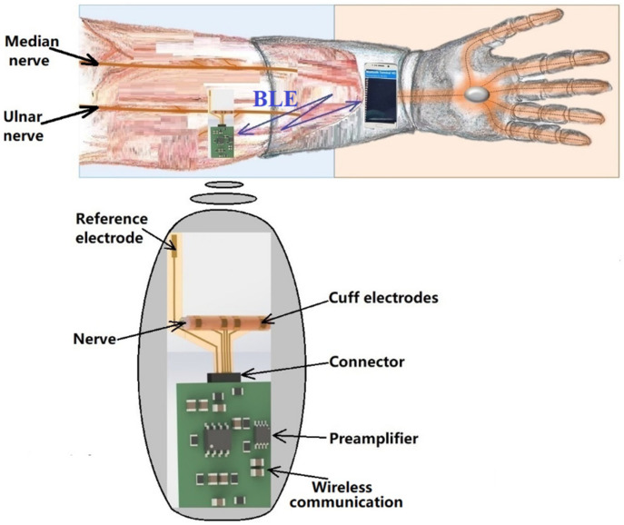
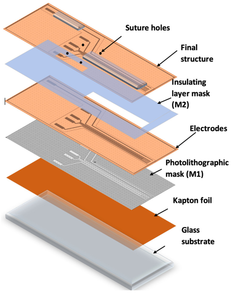
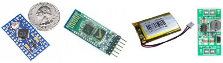
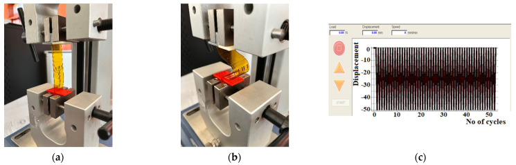
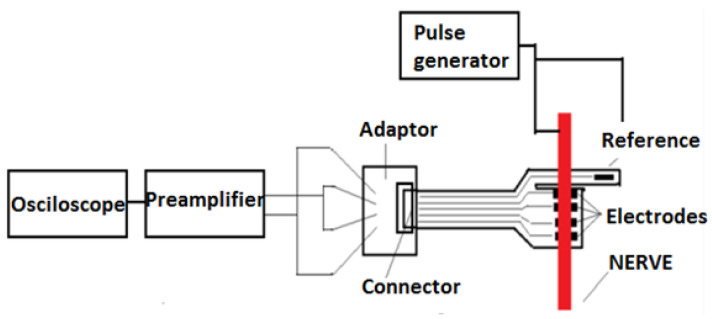
In this article, we present our research achievements regarding the development of a remote sensing system for motor pulse acquisition, as a first step towards a complete neuroprosthetic arm. We present the fabrication process of an implantable electrode for nerve impulse acquisition, together with an innovative wirelessly controlled system. In our study, these were combined into an implantable device for attachment to peripheral nerves. Mechanical and biocompatibility tests were performed, as well as in vivo testing on pigs using the developed system. This testing and the experimental results are presented in a comprehensive manner, demonstrating that the system is capable of accomplishing the requirements of its designed application. Most significantly, neural electrical signals were acquired and transmitted out of the body during animal experiments, which were conducted according to ethical regulations in the field.

Keywords: microfabrication; microsystem; microtechnology; neuroprosthesis.


Conflict of interest statement

The authors declare no conflict of interest.

Figures

Figure 1
Figure 1
The shape and characteristics of a motor nerve impulse.
Figure 2
Figure 2
The remote sensing system for motor nerve pulse acquisition.
Figure 3
Figure 3
Schematic view of the method and the technological flow of the electrode system.
Figure 4
Figure 4
(a) Layout of the proposed flexible electrodes and (b) fabricated electrodes.
Figure 5
Figure 5
The circuit diagram of the front-end module.
Figure 6
Figure 6
The front-end circuit board.
Figure 7
Figure 7
Arduino Mini, HC-05 Bluetooth module, iOptron Lithium-Poly 3.7 V battery, and the step-up DC-DC converter.
Figure 8
Figure 8
The bending cycles: (a) stretching and (b) bending the electrodes with MECMESIN MULTITEST 2.5.i; (c) diagram of the bending cycles.
Figure 9
Figure 9
Electrodes used as samples for the bending tests.
Figure 10
Figure 10
Measurements the electrodes resistance: (a) electrodes (b) FLUKE 8846 A multi-meter.
Figure 11
Figure 11
The flexible collar electrodes attached to the nerve.
Figure 12
Figure 12
Metabolic activity measured fluorescently after addition of PrestoBlue reagent. An * denotes statistical difference from the other groups (α = 0.1).
Figure 13
Figure 13
Nyquist diagrams (-Zi vs. Zr) taken over time for the electrode permanently immersed in the PBS 7.1 electrolyte solution for a frequency range between 100 mHz and 100 kHz at: 0 days (a); 1st day (b); 2nd day (c); 7th day (d); 14th day (e); 21st day (f). Inset: the equivalent circuit with: resistance charge transfer (Rct), capacitive dielectric double layer (Cdl), and resistance solution (Rs).
Figure 14
Figure 14
CVs (−800 mV–800 mV) of the electrodes in the electrolyte solution PBS 7.1 after: 0 day (a); 1st day (b); 7th day (c); 14th day (d); and 21st day (e).
Figure 15
Figure 15
Electrochemical impedance spectra of gold electrodes over 21 days of experiments, as a function of frequency: 0 day (a); 1st day (b); 2nd day (c); 7th day (d); 14th day (e); and 21st day (f).
Figure 16
Figure 16
Real impedance vs. time at 1 kHz.
Figure 17
Figure 17
Electrode resistance before and after bending.
Figure 18
Figure 18
Block diagram of the testing circuit.
Figure 19
Figure 19
Pulse generator used to induce movement of swine leg.
Figure 20
Figure 20
Installing the preamplifier (front-end electronics).
Figure 21
Figure 21
The block diagram of the experiment.
Figure 22
Figure 22
The block diagram of the electronic test module.
Figure 23
Figure 23
The signal recorded during the nerve stimulation.
Figure 24
Figure 24
The string of signals received on the mobile phone from the Bluetooth transmitter upon stimuli applied to nerve.

References

    1. Burck J.M., Bigelow J.D., Harshbarger S.D. Revolutionizing Prosthetics: Systems Engineering Challenges and Opportunities. Johns Hopkins APL Tech. Dig. 2011;30:186–197.
    1. Imenes K., Blystad L.C., Marchetti L., Hønsvall B.K., Øhlckers P., Rabbani S., Moldovan C., Ionescu O., Franti E., Dascalu M., et al. Implantable Interface for an Arm Neuroprosthesis; Proceedings of the European Microelectronics and Packaging Conference & Exhibition (EMPC); Gothenburg, Sweden. 13–16 September 2021.
    1. Naples G.G., Sweeney J.D., Mortimer J.T. Implantable Cuff, Method of Manufacture, and Method of Installation. 4602624A. U.S. Patent. 1986 July 29;
    1. Ortiz-Catalan M., Brånemark R., Håkansson B., Delbeke J. On the viability of implantable electrodes for the natural control of artificial limbs: Review and discussion. Biomed. Eng. Online. 2012;11:33. doi: 10.1186/1475-925X-11-33. - DOI - PMC - PubMed
    1. Struijk J.J., Thomsen M., Larsen J.O., Sinkjaer T. Cuff electrodes for long-term recording of natural sensory information. IEEE Eng. Med. Biol. Mag. 1999;18:91–98. doi: 10.1109/51.765194. - DOI - PubMed

LinkOut - more resources