. 2021:1:66.
doi: 10.1038/s43586-021-00065-8. Epub 2021 Oct 7.

Electrolyte-gated transistors for enhanced performance bioelectronics

Affiliations

Electrolyte-gated transistors for enhanced performance bioelectronics

Fabrizio Torricelli et al. Nat Rev Methods Primers. 2021.

Abstract

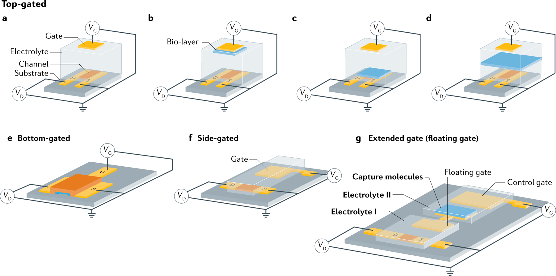
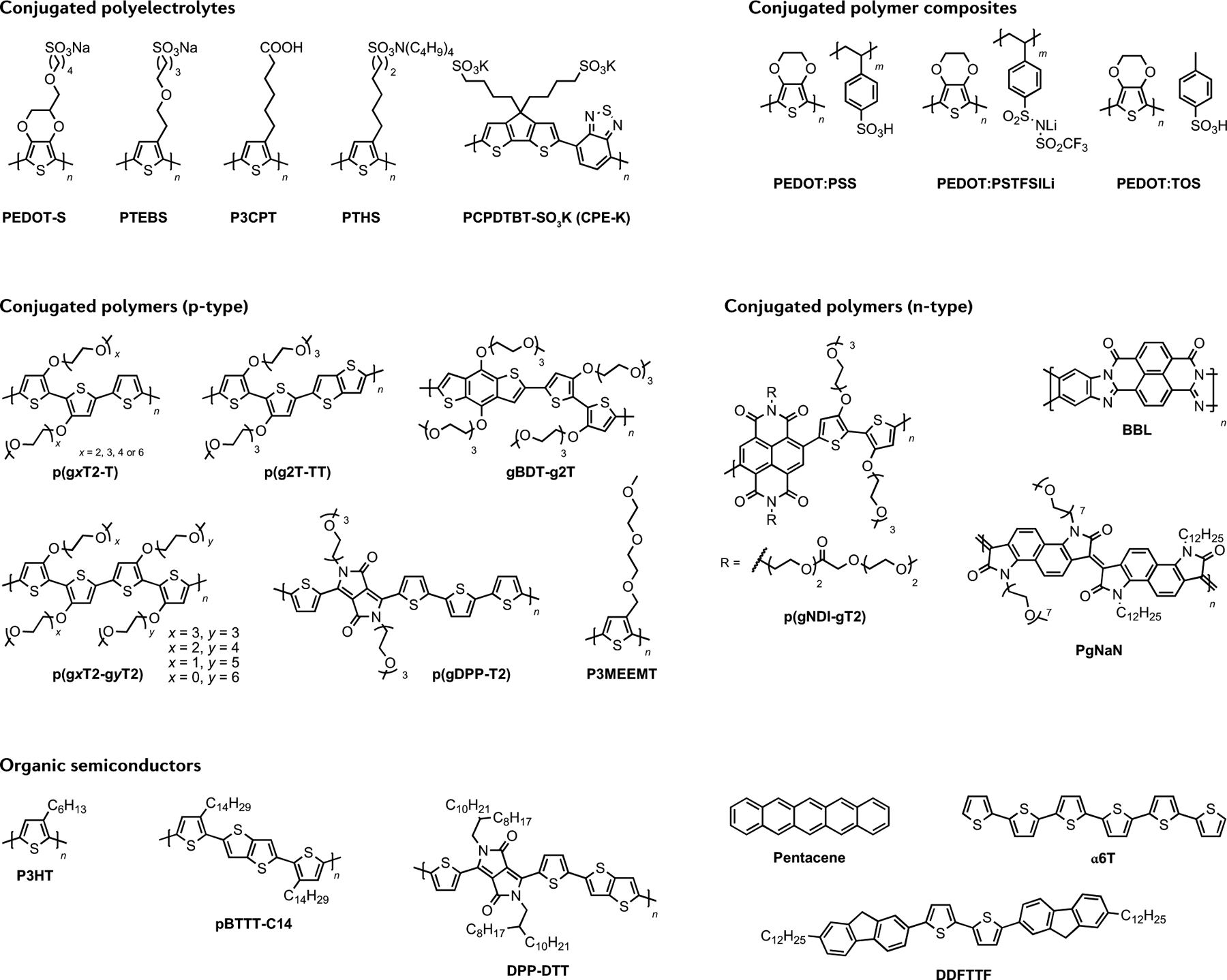
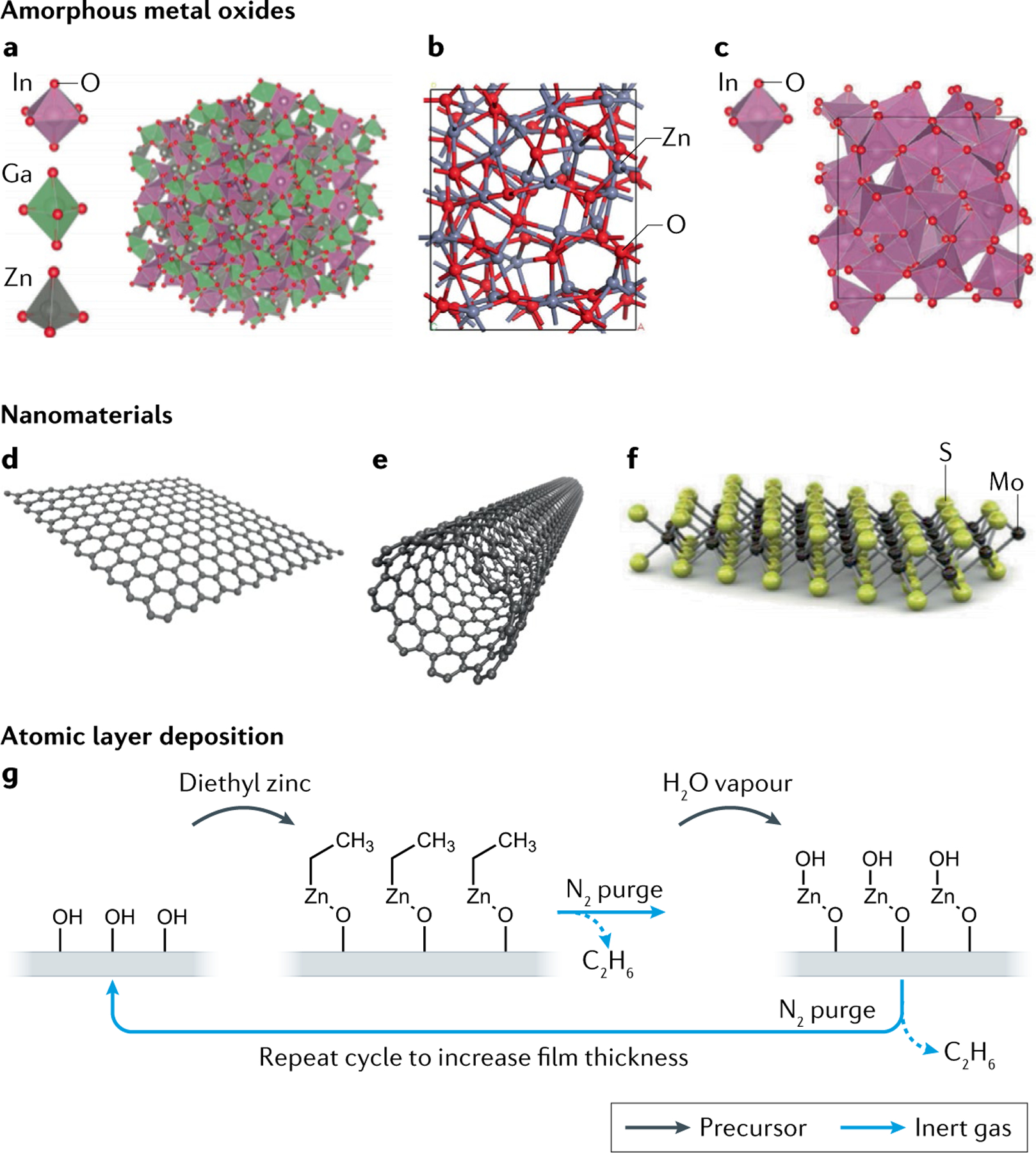
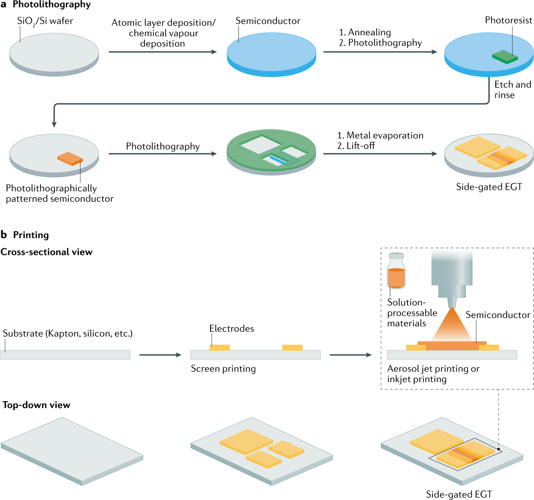
Electrolyte-gated transistors (EGTs), capable of transducing biological and biochemical inputs into amplified electronic signals and stably operating in aqueous environments, have emerged as fundamental building blocks in bioelectronics. In this Primer, the different EGT architectures are described with the fundamental mechanisms underpinning their functional operation, providing insight into key experiments including necessary data analysis and validation. Several organic and inorganic materials used in the EGT structures and the different fabrication approaches for an optimal experimental design are presented and compared. The functional bio-layers and/or biosystems integrated into or interfaced to EGTs, including self-organization and self-assembly strategies, are reviewed. Relevant and promising applications are discussed, including two-dimensional and three-dimensional cell monitoring, ultra-sensitive biosensors, electrophysiology, synaptic and neuromorphic bio-interfaces, prosthetics and robotics. Advantages, limitations and possible optimizations are also surveyed. Finally, current issues and future directions for further developments and applications are discussed.


Conflict of interest statement

Competing interests The authors declare no competing interests.

Figures

Fig. 1 |
Fig. 1 |. EGTs for enhanced bioelectronics.
Basic architectures of an electrolyte-gated transistor (EGT). Various components, such as the gate, electrolyte, source, semiconducting channel and drain, are highlighted. VG, VD and VS are the gate, drain and source voltage, respectively. a | Top-gated architecture. b | Top-gated EGT with a bio-layer on the gate electrode. The gate is a polarizable electrode. c | Top-gated EGT with a bio-layer on the transistor channel. The gate can be a polarizable or non-polarizable (for example, reference) electrode. d | Top-gated EGT with a bio-layer included in the electrolyte. The bio-layer separates the electrolyte in two compartments. The gate can be a polarizable or non-polarizable electrode. e | Bottom-gated EGT architecture. f | Side-gated EGT architecture. g | Extended gate (or floating gate) EGT architecture.
Fig. 2 |
Fig. 2 |. Typical organic materials used for EGTs.
Various classes of organic semiconductors (OSCs) developed for organic electrochemical transistors (OECTs) (conjugated polyelectrolytes (CPEs), conjugated polymer composites and conjugated polymers) and OSCs used for electrolyte-gated transistors (EGTs). α6T, α-sexithiophene; BBL, poly(benzimidazobenzophenanthroline); DDFTTF, 5,5′-bis-(7-dodecyl-9H-fluoren-2-yl)-2,2′-bithiophene; DPP-DTT, poly[2,5-(2-octyldodecyl)-3,6-diketopyrrolopyrrole-alt-5,5-(2,5-di(thien-2-yl)thieno[3,2-b]thiophene)]; gBDT-g2T, poly(2-(3,3′-bis(triethylene glycol monomethyl ether)-[2,2′-bithiophen]-5-yl)-(4,8-bis(triethylene glycol monomethyl ether)benzo[1,2-b:4,5-b’]dithiophene-2,6-diyl)); P3CPT, poly(3-carboxypentylthiophene); P3HT, poly(3-hexylthiophene); P3MEEMT, poly(3-{[diethylene glycol monomethyl ether]methyl}thiophene); p(gNDI-gT2), poly{[N,N′-naphthalene-1,4,5,8-bis(dicarboximide)-2,6-diyl]-alt-5,5′-(3,3′-bis(methoxy)-[2,2′-bithiophen]-5-yl)}; pBTTT-C14, poly[2,5-bis(3-tetradecylthiophen-2-yl)thieno[3,2-b]thiophene]; PCPDTBT-SO3K, poly[2,6-(4,4-bis-potassium butanylsulfonate-4H-cyclopenta-[2,1-b;3,4-b’]-dithiophene)-alt-4,7-(2,1,3-benzothiadiazole)]; PEDOT:PSS, poly(3,4-ethylenedioxythiophene) polystyrene sulfonate; PEDOT:PSTFSILi, poly(3,4-ethylenedioxythiophene) potassium poly[4-styrenesulfonyl(trifluoromethyl sulfonyl) imide]; PEDOT-S, sodium poly(4-(2,3-dihydrothieno[3,4-b][1,4]dioxin-2-yl-methoxy)-1-butylsulfonate); PEDOT:TOS, poly(3,4-ethylenedioxythiophene) tosylate; p(g3T2), poly(2-(3,3′-bis(triethylene glycol monomethyl ether)-[2,2′-bithiophen]-5-yl)); p(g0T2-g6T2), poly(2-(3,3′-bis(methoxy)-[2,2′-bithiophen]-5-yl))-(2-(3,3′-bis(hexaethylene glycol monomethyl ether)-[2,2′-bithiophen]-5-yl)); p(g1T2-g5T2), poly(2-(3,3′-bis(monoethylene glycol monomethyl ether)-[2,2′-bithiophen]-5-yl))-(2-(3,3′-bis(pentaethylene glycol monomethyl ether)-[2,2′-bithiophen]-5-yl)); p(g2T2-g4T2), poly(2-(3,3′-bis(diethylene glycol monomethyl ether)-[2,2′-bithiophen]-5-yl))-(2-(3,3′-bis(tetraethylene glycol monomethyl ether)-[2,2′-bithiophen]-5-yl)); p(g2T2-T), poly(2-(3,3′-bis(diethylene glycol monomethyl ether)-[2,2′-bithiophen]-5-yl)thiophene); p(g3T2-T), poly(2-(3,3′-bis(triethylene glycol monomethyl ether)-[2,2′-bithiophen]-5-yl)thiophene); p(g4T2-T), poly(2-(3,3′-bis(tetraethylene glycol monomethyl ether)-[2,2′-bithiophen]-5-yl)thiophene); p(g6T2-T), poly(2-(3,3′-bis(hexaethylene glycol monomethyl ether)-[2,2′-bithiophen]-5-yl)thiophene); p(g2T-TT), poly(2-(3,3′-bis(triethylene glycol monomethyl ether)-[2,2′-bithiophen]-5-yl)thieno[3,2-b]thiophene); p(gDPP-T2), poly((3,6-bis(5-thien-2-yl)-2,5-di(triethylene glycol monomethyl ether)-2,5-dihydropyrrolo[3,4-c] pyrrole-1,4-dione)2,2′-bithiophene); PgNaN, poly([3,8-di-(heptaethylene glycol monomethyl ether)-3,8-dihydroindolo[7, 6-g]indole-2,7-dione]-[3,8-didodecyl-1,3,6,8-tetrahydroindolo[7, 6-g]indole-2,7-dione]); PTEBS, sodium poly[2-(3-thienyl)-ethoxy-4-butylsulfonate]; PTHS, tetrabutylammonium poly(6-(thiophene-3-yl)hexane-1-sulfonate).
Fig. 3 |
Fig. 3 |. Typical inorganic semiconductors used for EGTs.
a | Amorphous structure of indium–gallium–zinc oxide (IGZO). b | Structure of amorphous zinc oxide (ZnO). c | Structure of amorphous indium oxide (InO3). d | Two-dimensional layer of the semimetal graphene. e | Single-walled carbon nanotubes. f | Two-dimensional molybdenum disulfide (MoS2). g | Atomic layer deposition is one method to deposit thin films of inorganic semiconductors on a substrate. Precursors injected into the chamber react with the surface of the substrate, building the film up layer by layer. Purge steps in between with inert gas remove by-products and undesired precursor from the chamber. Atomic layer deposition ultimately enables control over film thickness and uniformity. EGT, electrolyte-gated transistor. Part a adapted with permission from REF., ACS. Part b adapted from REF., CC BY 4.0 (https://creativecommons.org/licenses/by/4.0/). Part c adapted with permission from REF., Wiley. Parts d and e adapted from REF., CC BY 4.0 (https://creativecommons.org/licenses/by/4.0/). Part f adapted with permission from REF., Elsevier.
Fig. 4 |
Fig. 4 |. Fabrication of EGTs.
Fabrication of side-gated electrolyte-gated transistor (EGT). a | Conventional fabrication utilizing common deposition methods for semiconductor film growth and photolithography for selective patterning of the semiconductor and electrodes. Necessary equipment includes spin-coater, mask aligner, vacuum deposition chamber and vacuum evaporator chamber. Photolithography is typically performed on silicon, glass, ceramic and plastic substrates. Miniaturized devices with high-resolution features can be obtained. b | Unconventional fabrication utilizing additive processes including screen printing, aerosol jet printing and inkjet printing. Necessary equipment includes aerosol jet, inkjet, gravure and/or screen printer. Printing methods are suitable for glass, ceramic, plastic, textile and paper substrates. Fabricated devices can be flexible, wearable, on a large area and of low cost.
Fig. 5 |
Fig. 5 |. Integration of bio-layers in EGTs.
ac | Immobilization of bio-recognition elements on a solid surface by means of physical adsorption (part a), self-assembled monolayer (SAM) (part b) and stepwise deposition of biological species with opposite charges (part c). d | Bio-affinity immobilization based on biotin-tagged bio-recognition elements and streptavidin immobilized on a solid surface. e | Bio-affinity immobilization used for the orientation of biomolecules on a solid surface. EGT, electrolyte-gated transistor.
Fig. 6 |
Fig. 6 |. Representative electrical characteristics of EGTs.
a | Typical transfer characteristics IDVG at various VD of a p-type ion-permeable and depletion-mode electrolyte-gated transistor (EGT) (full lines). Transconductance gm and threshold voltage VT are highlighted (dashed line) in the case VD = −0.3 V. b | Typical transfer characteristics IDVG at various VD of an n-type ion-impermeable and accumulation-mode EGT (full lines). c | Typical output characteristics IDVD at various VG of a p-type ion-permeable and depletion-mode EGT. d | Typical output characteristics IDVD at various VG of an n-type ion-impermeable and accumulation-mode EGT. e | Schematic lumped circuit model of a bare EGT (without bio-layer). f | Typical gm as a function of VG at several VD in the case of a p-type ion-permeable and depletion-mode EGT. Maximum of gm depends on both VG and VD. g | Typical gm as a function of VG at several VD in the case of an n-type ion-impermeable and accumulation-mode EGT. h | EGT lumped model highlighting the bio-layer on the gate electrode. Position of the bio-layer schematically depicted by the cyan area. i | Typical IDVG curves in the case of selective bio-recognition taking place at the bio-layer on the gate electrode. By the way of example, these characteristics could be obtained with EGT biosensors with bio-functionalized gate. j | EGT lumped model highlighting the bio-layer on the channel. k | Typical IDVG curves in the case of biological events taking place on the channel mainly result in variation of bio-layer capacitance. These characteristics could be obtained when EGT is used for cell monitoring as well as EGT biosensors. l | EGT lumped model highlighting the bio-layer embedded in the electrolyte. m | Typical transient response obtained when the bio-layer results in a variation of the ionic resistance and/or capacitance, as for example when monitoring the cells grow and barrier integrity. n | EGT lumped model highlighting the external electrical connection between the EGT and the biology during electrophysiological measurements. o | Typical frequency response of an ion-permeable EGT. CCH, transistor channel capacitance; CG, gate capacitance; ID, drain current; REL, electrolyte resistance; RG, gate resistance; VD, drain voltage; VG, gate voltage; VS, source voltage.
Fig. 7 |
Fig. 7 |. Three-dimensional cell monitoring, ultra-sensitive biosensors and in vivo electrophysiology using EGTs.
a | Three-dimensional confocal microscopy image of cardiac spheroid labelled with Ca2+ indicator dye (Fluo-4, green fluorescence) encapsulated by the 3D-SR-BA. The numbers are the micro-electrodes labels. Scale bar, 50 μm. b | Three-dimensional conducting polymer transistors in a tube named Tubistor. The device is composed of a tubular cavity with three openings, gold-coated flexible electrodes used as source and drain contacts of the channel fixed inside the tube, and a poly(3,4-ethylenedioxythiophene) polystyrene sulfonate (PEDOT:PSS) channel. Length L = 1 mm and width W = 4 mm. Gate electrode embedded inside the tube. c | COVID-19 electrolyte-gated transistor (EGT) sensor operation procedure. Graphene serves a sensing material and SARS-CoV-2 spike antibody is covalently attached to the graphene sheet via 1-pyrenebutyric acid N-hydroxysuccinimide ester, which is an interfacing molecule serving as probe linker. d | Single-Molecule assay with a large-area Transistor (SiMoT) EGT transfer characteristics. Dashed grey curve corresponds to anti-human IgG capturing layer incubated in the bare phosphate saline buffer (PBS) solution. Same gate is further exposed, in sequence, to PBS standard solutions of IgG at different concentrations. e | Wiring diagram for electrocardiographic recording with bio-resorbable EGT operated in direct contact with the skin and photograph of four organic electrochemical transistors (OECTs) showing their adaptability when attached to human skin. f | Micrograph of an implantable device with four EGTs. g | Micrograph of an EGT conforming to human scalp (scale bar, 2 mm). BSA, bovine serum albumen; ID, drain current; SAM, self-assembled monolayer; VDS, drain–source voltage; VG, gate voltage; VGS, gate–source voltage; VT, threshold voltage. Part a reprinted with permission of AAAS from REF.. © The Authors, some rights reserved; exclusive licensee AAAS. Distributed under a CC BY-NC 4.0 License (http://creativecommons.org/licenses/by-nc/4.0/). Part b reprinted with permission of AAAS from REF.. © The Authors, some rights reserved; exclusive licensee AAAS. Distributed under a CC BY-NC 4.0 License (http://creativecommons.org/licenses/by-nc/4.0/). Part c adapted with permission from REF., ACS. Part d adapted from REF., Springer Nature Limited. Part e adapted with permission from REF., Wiley. Part f adapted from REF., Springer Nature Limited. Part g reprinted with permission of AAAS from REF.. © The Authors, some rights reserved; exclusive licensee AAAS. Distributed under a CC BY-NC 4.0 License (http://creativecommons.org/licenses/by-nc/4.0/).
Fig. 8 |
Fig. 8 |. Synaptics and neuromorphics with EGTs.
a | Schematic synaptic organic electrochemical transistor (OECT) in analogy with a biological synapse. b | Example of a pair of presynaptic pulses (VPre) applied at the OECT gate electrode and the postsynaptic drain current (IPost) measured as a function of time. Amplitude, A, of IPost exhibits paired pulse depression behaviour. c | Biological afferent nerve stimulated by pressure. Action potentials from multiple nerve fibres combine through synapses and contribute to information processing. d | Schematic structure of an artificial afferent nerve. EGT, electrolyte-gated transistor; PEDOT:PSS, poly(3,4-ethylenedioxythiophene) polystyrene sulfonate; VDS, drain–source voltage. Parts a and b adapted with permission from REF., Wiley. Parts c and d adapted with permission from REF., AAAS.

References

    1. Willner I & Katz E (eds) Bioelectronics: From Theory to Applications (Wiley, 2005).
    1. Hess LH, Seifert M & Garrido JA Graphene transistors for bioelectronics. Proc. IEEE 101, 1780–1792 (2013).
    1. Zhou W, Dai X & Lieber CM Advances in nanowire bioelectronics. Rep. Prog. Phys 80, 16701 (2016). - PubMed
    1. Rivnay J et al. Organic electrochemical transistors. Nat. Rev. Mater 3, 17086 (2018).
    2. This review provides an overview of OECTs.

    1. Wang N, Yang A, Fu Y, Li Y & Yan F Functionalized organic thin film transistors for biosensing. Acc. Chem. Res 52, 277–287 (2019). - PubMed

LinkOut - more resources