Case Reports
. 2022 Mar 16;4(6):343-347.
doi: 10.1016/j.jaccas.2022.01.005.

Transcatheter Treatment of Ascending Aorta Pseudoaneurysm Guided by 3D-Model Technology

Affiliations
Case Reports

Transcatheter Treatment of Ascending Aorta Pseudoaneurysm Guided by 3D-Model Technology

Giuseppe Santoro et al. JACC Case Rep. .

Abstract

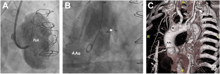
Ascending aorta pseudoaneurysm is a rare but potentially life-threatening complication of atherosclerosis, infections, chest trauma, transcatheter or surgical interventions. Due to high surgical risk, percutaneous closure is considered a valuable cost-effective therapeutic alternative. In this setting, 3D printing technology is emerging as a powerful tool to plan transcatheter repair. (Level of Difficulty: Advanced.).

Keywords: 3D printing; 3D, 3-dimensional; AAP, ascending aorta pseudoaneurysm; CT, computed tomography; aorta; device; pseudoaneurysm.


Conflict of interest statement

Dr Santoro has been a proctor for Abbott, WL Gore, and Occlutech. Dr Berti has been a proctor for Abbott, Boston Scientific, and Edwards. All other authors have reported that they have no relationships relevant to the contents of this paper to disclose.

Figures

None
Graphical abstract
Figure 1
Figure 1
3D Computed Tomography Scan and Printed Model of the Huge Pseudoaneurysm Compressing the Anterior Surface of the Ascending Aorta Ascending aorta pseudoaneurysm as imaged at computed tomography scan 3D reconstruction from outside (A) and by cut-plain internal views (B). Using the cut-plain internal view, it is possible to precisely size the feeding breach of the pseudoaneurysm (asterisk). Printed 3D model of the ascending aorta and pseudoaneurysm as viewed en face (C) and from behind (D). AAo =ascending aorta; Dao = descending aorta; LPA = left pulmonary artery; LV = left ventricle; PA = main pulmonary artery; PsA = pseudoaneurysm; RV = right ventricle.
Figure 2
Figure 2
Angiographic and 3D Computed Tomography Scan Imaging of the Pseudoaneurysm Submitted to Device Closure Angiographic appearance of the pseudoaneurysmal sac at the “in-situ” angiography (A). Angiographic (B) and computed tomography scan 3D reconstruction (C) of the ascending aorta after occlusion with the ASO device (asterisk). AAo = ascending aorta; PsA = pseudoaneurysm.
Figure 3
Figure 3
3D Computed Tomography Scan and Printed Model of the Pseudoaneurysmal Pouch Located at the Anterior Surface of the Transverse Aortic Arch Angio-computed tomography scan 3D reconstruction of the ascending aorta showing a small pseudo-aneurysm (asterisk) as viewed from outside (A). Using the cut-plain internal view (B), it is possible to image shape and size of its feeding mouth (arrow). Printed 3D model of the ascending aorta pseudoaneurysm as viewed en face (C) and from behind (D). AAo = ascending aorta; Dao = descending aorta; TAoA = transverse aortic arch.
Figure 4
Figure 4
Angiographic and 3D Computed Tomography Scan Imaging of the Pseudoaneurysm Submitted to Device Closure Pseudoaneurysmal sac (asterisk) as imaged by in situ angiography (A). Complete occlusion of the pseudoaneurysm after device implantation (arrow) as imaged at aortic angiography (B) and pre-discharge computed tomography scan 3D reconstruction (C). AAo = ascending aorta; DAo = descending aorta.
Figure 5
Figure 5
3D Computed Tomography Scan and Printed Model of the Pseudoaneurysmal Sac Located at the Posterolateral Surface of the Ascending Aorta Pseudoaneurysm (asterisk) of the posterior side of the ascending aorta as imaged at computed tomography scan 3D reconstruction from outside (A) and by cut-plain internal view (B). Printed 3D model of the ascending aorta pseudoaneurysm as viewed from behind (C) and above (D). AAo = ascending aorta; DAo = descending aorta; LV = left ventricle; RA = right atrium; RV = right ventricle; TAoA = transverse aortic arch.
Figure 6
Figure 6
Angiographic and 3D Computed Tomography Scan Imaging of the Pseudoaneurysm Submitted to Device Closure Aortic angiography in right oblique view before (A, B) and after (C) closure of the pseudoaneurysmal sac with multiple devices. Complete occlusion of the pseudoaneurysm after device implantation as imaged at the predischarge computed tomography scan 3D reconstruction (D). AAo = ascending aorta; D = devices; LV = left ventricle.

References

    1. Belkin R.N., Kalapatapu S.K., Lafaro R.J., Ramaswamy G., McClung J.A., Cohen M.B. Atherosclerotic pseudoaneurysm of the ascending aorta. J Am Soc Echocardiogr. 2003;16:367–369. - PubMed
    1. Razzouk A.A., Gundry S., Wang N., et al. Pseudoaneurysms of the aorta after cardiac surgery or chest trauma. Am J Surg. 1993;59:818–823. - PubMed
    1. Navaravong L., Saab F., Cook J.R., Peterman M., Flack J. Ascending aortic pseudoaneurysm, a ticking bomb after cardiac surgery. Cardiovasc Revasc Med. 2011;12:177–180. - PubMed
    1. Bashir F., Quaife R., Carroll J.D. Percutaneous closure of ascending aorta pseudoaneurysm using Amplatzer septal occluder device: the first clinical case report and literature review. Cathet Cardiovasc Interv. 2005;65:547–551. - PubMed
    1. Vukicevica M., Mosadeghb B., Minb J.K., Little S.H. Cardiac 3D printing and its future directions. J Am Coll Cardiol Img. 2017;10:171–184. - PMC - PubMed

Publication types

LinkOut - more resources