. 2022 Jul;34(28):e2202261.
doi: 10.1002/adma.202202261. Epub 2022 Jun 4.

Simultaneous One-Pot Interpenetrating Network Formation to Expand 3D Processing Capabilities

Affiliations

Simultaneous One-Pot Interpenetrating Network Formation to Expand 3D Processing Capabilities

Abhishek P Dhand et al. Adv Mater. 2022 Jul.

Abstract

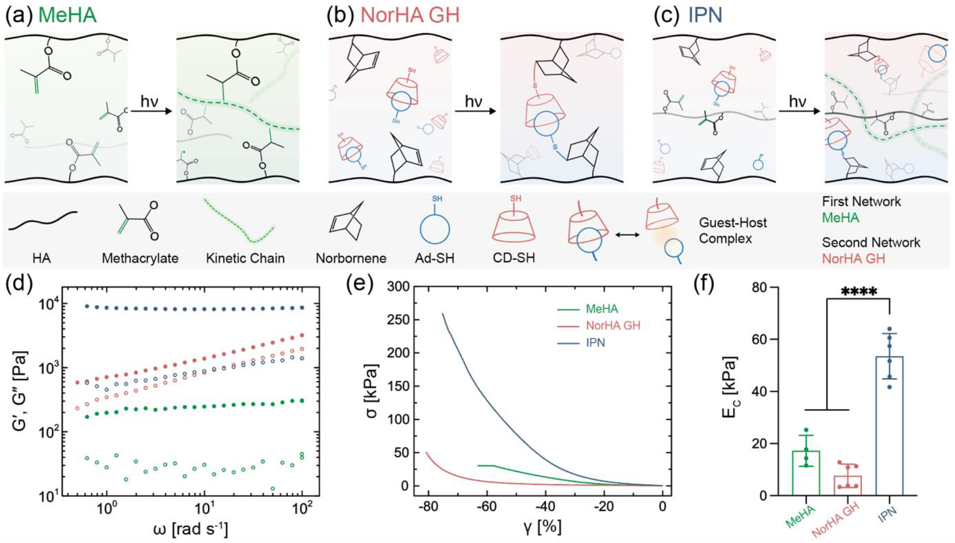
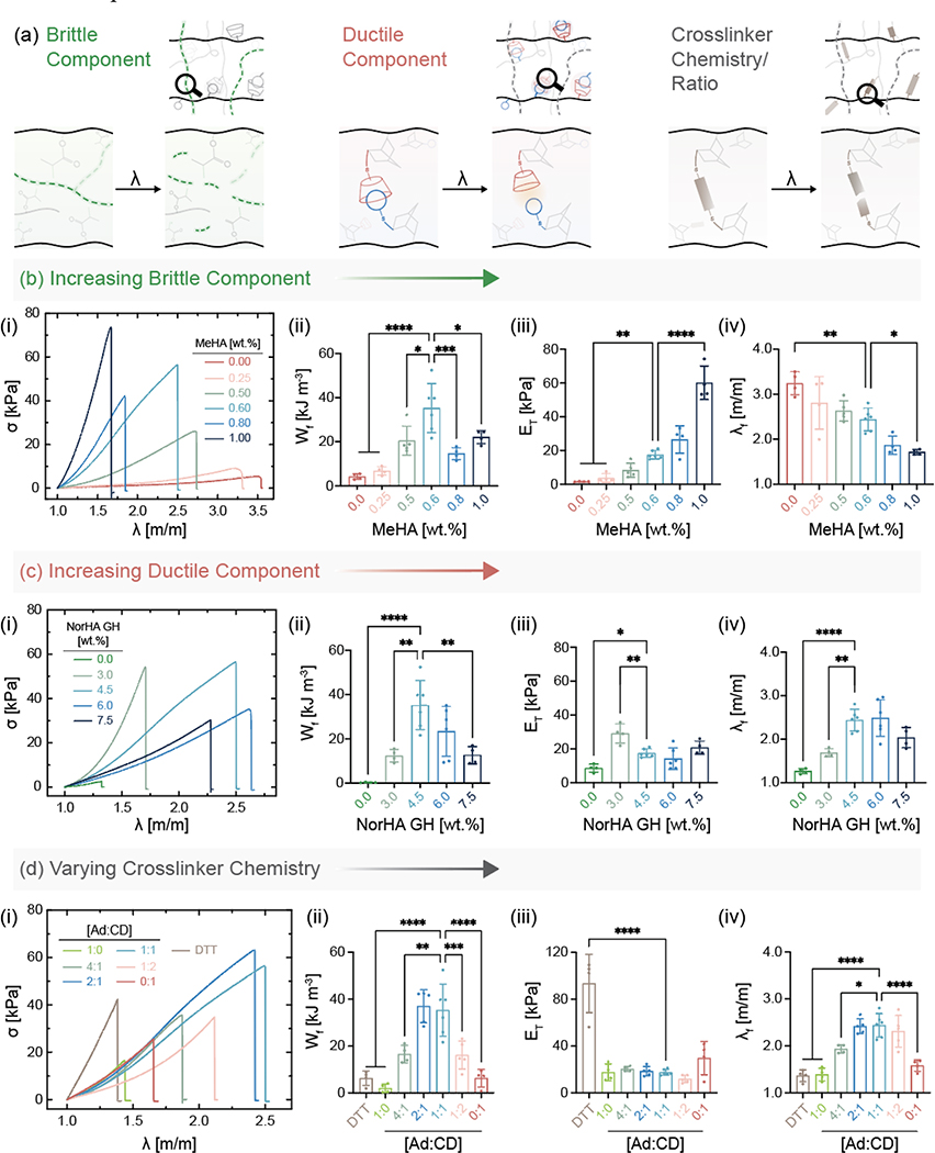
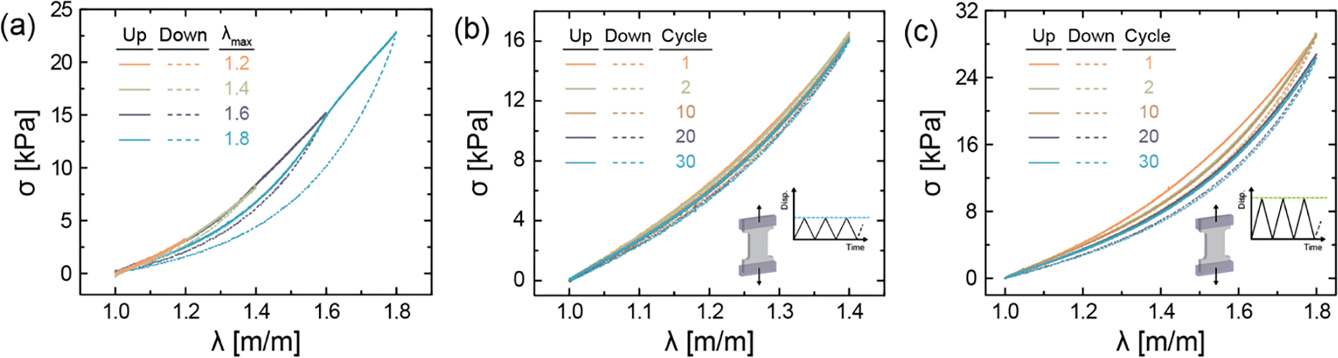
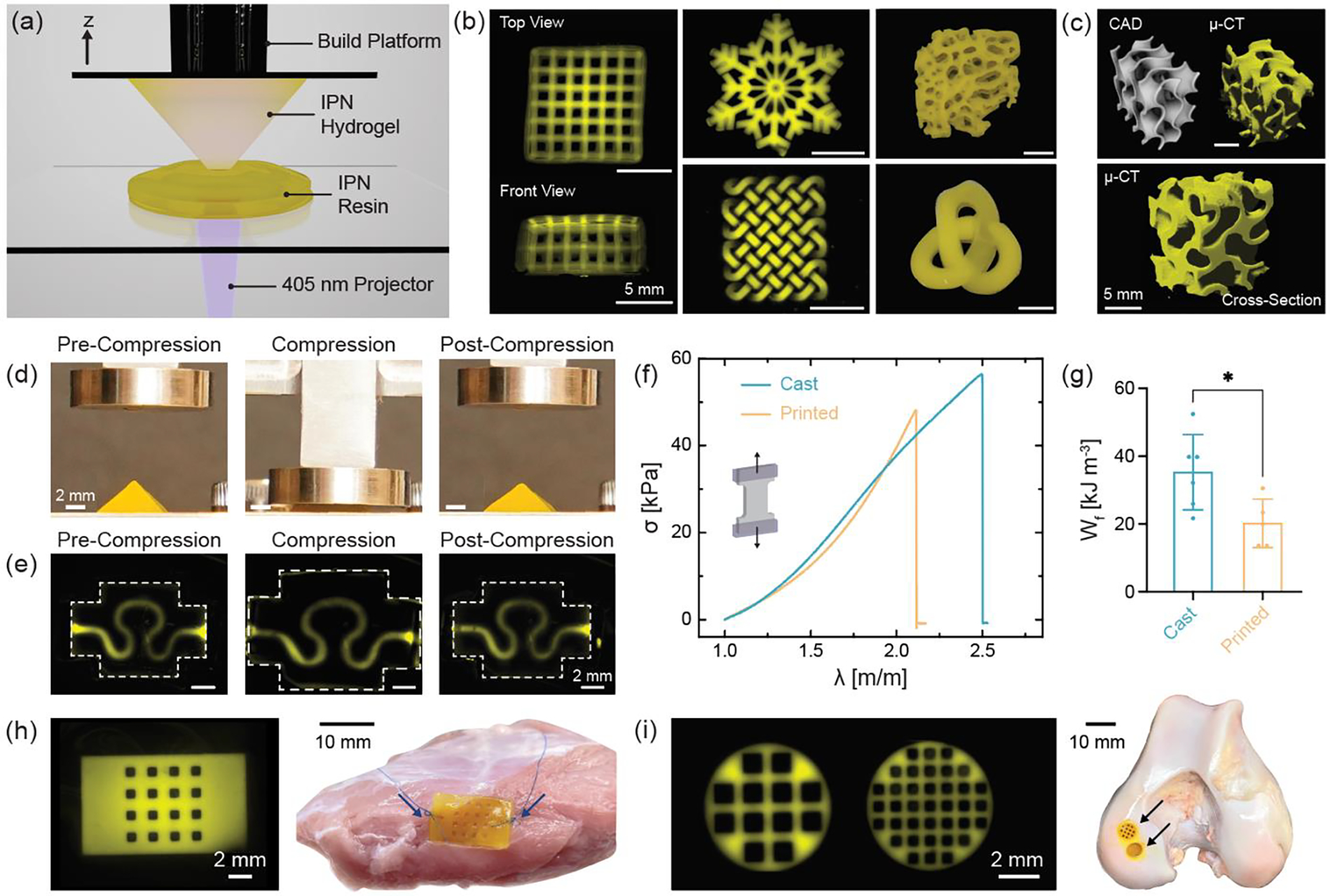
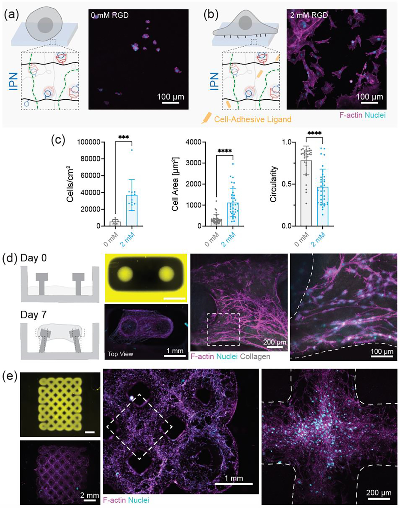
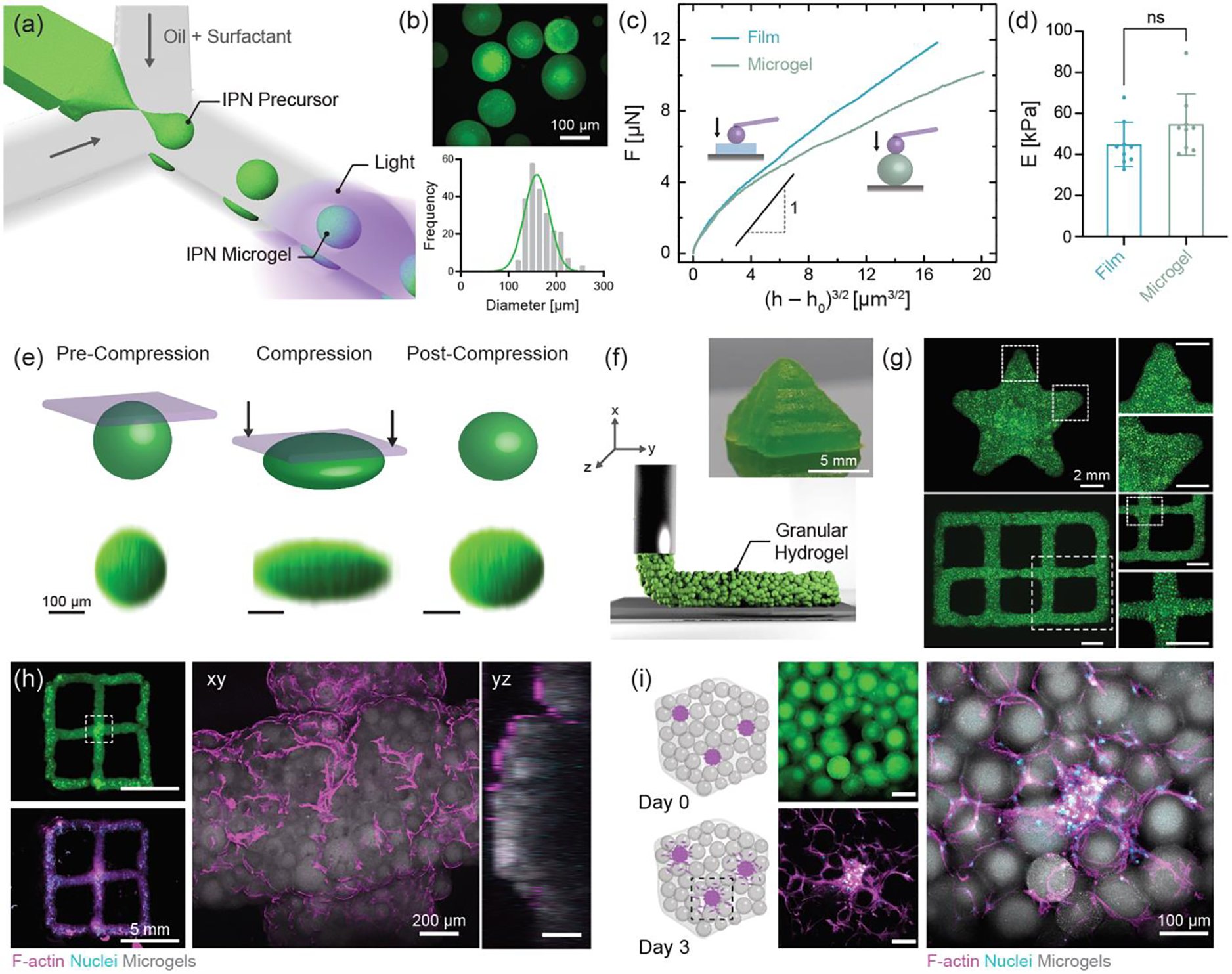
The incorporation of a secondary network into traditional single-network hydrogels can enhance mechanical properties, such as toughness and loading to failure. These features are important for many applications, including as biomedical materials; however, the processing of interpenetrating polymer network (IPN) hydrogels is often limited by their multistep fabrication procedures. Here, a one-pot scheme for the synthesis of biopolymer IPN hydrogels mediated by the simultaneous crosslinking of two independent networks with light, namely: i) free-radical crosslinking of methacrylate-modified hyaluronic acid (HA) to form the primary network and ii) thiol-ene crosslinking of norbornene-modified HA with thiolated guest-host assemblies of adamantane and β-cyclodextrin to form the secondary network, is reported. The mechanical properties of the IPN hydrogels are tuned by changing the network composition, with high water content (≈94%) hydrogels exhibiting excellent work of fracture, tensile strength, and low hysteresis. As proof-of-concept, the IPN hydrogels are implemented as low-viscosity Digital Light Processing resins to fabricate complex structures that recover shape upon loading, as well as in microfluidic devices to form deformable microparticles. Further, the IPNs are cytocompatible with cell adhesion dependent on the inclusion of adhesive peptides. Overall, the enhanced processing of these IPN hydrogels will expand their utility across applications.

Keywords: Digital Light Processing; hydrogels; interpenetrating polymer networks; microparticles; photo-crosslinking.


Figures

Figure 1.
Figure 1.
Interpenetrating polymer network (IPN) hydrogels formed via one-pot, light triggered orthogonal reactions. Schematic illustration of chemistry involved in (a) free radical crosslinking of methacrylate modified hyaluronic acid (MeHA) single network (SN), (b) photo-initiated thiol-ene reaction between norbornene modified HA (NorHA) and adamantane thiol (Ad-SH) and β-cyclodextrin thiol (CD-SH) to form a network with guest-host (GH) crosslinks, resulting in a NorHA GH SN, and (c) IPN consisting of simultaneous formation of MeHA (first, brittle) and NorHA GH (second, ductile) networks. Representative profiles of (d) G′ (closed) and G″ (open) as a function of angular frequency and (e) compressive stress-strain response, as well as (f) quantified compressive modulus (EC) for SNs of MeHA (0.6 wt.%) and NorHA GH (4.5 wt.%), and an IPN comprised of these same SN formulations. Data are reported as mean ± SD; n ≥ 4; ****p < 0.0001 (one-way ANOVA).
Figure 2.
Figure 2.
Influence of network composition and chemistry on mechanical properties of IPN hydrogels. (a) Various parameters within IPNs that are important to overall material properties. (b) Increasing MeHA (brittle network) concentration at a fixed NorHA GH concentration. (i) Stress (σ)-stretch (λ) curves of samples stretched uniaxially to rupture, (ii) work of fracture (Wf), (iii) tensile modulus (ET), and (iv) stretch at failure (λf) for IPN hydrogels with varying MeHA concentration and constant NorHA GH concentration (4.5 wt.%). Statistical comparisons of all groups to only the MeHA (0.6 wt.%) group shown on graphs. (c) Increasing NorHA GH (ductile network) concentration at a fixed MeHA concentration. (i) Stress-stretch curves of samples stretched uniaxially to rupture, (ii) Wf, (iii) ET, and (iv) λf for IPN hydrogels with varying NorHA GH concentrations and constant MeHA concentration (0.6 wt.%). Statistical comparisons of all groups to only the NorHA GH (4.5 wt.%) group shown on graphs. (d) Varying crosslinker chemistry (DTT) and crosslinker ratio (Ad:CD) at a fixed MeHA and NorHA GH concentration. (i) Stress-stretch curves of samples stretched uniaxially to rupture, (ii) Wf, (iii) ET, and (iv) λf for IPN hydrogels at constant MeHA (0.6 wt.%) and NorHA GH (4.5 wt.%) concentration. Statistical comparisons of all groups to only Ad:CD (1:1) group shown on graphs. Data are reported as mean ± SD; n ≥ 4; *p < 0.05; **p < 0.01; ***p < 0.001; ****p < 0.0001 (one-way ANOVA).
Figure 3.
Figure 3.
IPN hydrogels subjected to loading and unloading. Representative (a) stress-stretch curves of the same sample subjected to increasing stretch with each cycle (λ = 1.2 to 1.8). Stress-stretch curves of IPN hydrogels subjected to cyclic loading (up to 30 cycles) at constant stretch of (b) λ = 1.4 (λ < λc) and (c) λ = 1.8 (λ > λc) to assess damage. IPN hydrogel composition is kept fixed at MeHA (0.6 wt.%) and NorHA GH (4.5 wt.%) for all studies. Data are reported as mean ± SD; n ≥ 3.
Figure 4.
Figure 4.
3D processing of IPN resin into complex shapes using one-step light triggered orthogonal reactions. (a) Schematic representation of digital light processing (DLP) stereolithography fabrication of IPN hydrogel structures. (b) Fluorescence images of macroporous lattice (top and front views), snowflake, and knotted mesh structures and photographs of trabecular bone and 3D knot printed with IPN resin. Scale bar: 5 mm. (c) CAD and μ-CT rendering of gyroid 3D printed with IPN resin. Scale bars: 5 mm. Shape-recovery ability of (d) pyramid and (e) serpentine microfluidic device before, during, and after compression to ~65% strain. Scale bars: 2 mm. (f) Stress-stretch curves until failure and (g) work of fracture (Wf) for casted and 3D printed dog-bone specimens. Data are reported as mean ± SD; n ≥ 5; *p < 0.05 (two-tailed t-test). (h) 3D printed porous patch sutured to bovine skeletal muscle. Arrows indicate suture location. Scale bars: 2 mm and 10 mm. (i) 3D printed macroporous discs implanted into a bovine femoral condyle defect. Arrows indicate site of implantation. Scale bars: 2 mm and 10 mm. IPN hydrogel composition is kept fixed at MeHA (0.6 wt.%) and NorHA GH (4.5 wt.%) for all studies.
Figure 5.
Figure 5.
Cell interactions with 3D printed IPN hydrogels. Schematic representation and maximum projection image of 3T3 fibroblasts on IPN hydrogels with (a) 0 mM RGD (absence of cell adhesive ligands) and (b) 2 mM RGD (presence of cell adhesive ligands). Scale bars: 100 μm. (c) Quantification of the number of cells per unit area, cell spread area, and circularity of cells from (a) and (b). Data are reported as mean ± SD; n ≥ 8; ***p < 0.001; ****p < 0.0001 (two-tailed t-test). (d) Schematic representation of 3D printed mold for formation of collagen microtissue. Collagen gels seeded with fibroblasts at day 0 undergo contraction to form a dense tissue by day 7. Fluorescence images of 3D printed mold (yellow) at day 0 and tissue at day 7. Maximum projection images of microtissue to visualize cell morphology. Scale bars (left to right): 1 mm, 200 μm, and 100 μm. (e) Fluorescence images of 3D printed macroporous lattice (yellow) at day 0 and cellularization at day 1. Maximum projection images of lattice to visualize cell morphology. Scale bars (left to right): 2 mm, 1 mm, and 200 μm. F-actin (magenta), nuclei (cyan). IPN hydrogel composition was kept fixed at MeHA (0.6 wt.%) and NorHA GH (4.5 wt.%) for all studies
Figure 6.
Figure 6.
3D processing of IPN precursor into microparticles using one-step light triggered orthogonal reactions (a) Schematic representation of microfluidic fabrication of IPN microgels. (b) Fluorescence image and size distribution of IPN microgels. Scale bar: 100 μm. (c) Force (F) as a function of effective indentation, (h − h0)3/2 and (d) Young’s modulus (E) for casted IPN hydrogel films and IPN microgels. Data are reported as mean ± SD; n ≥ 8; ns = not significant (two-tailed t-test). Representative (e) shape-recovery of IPN microgel shown before, during (Force = 1.96 N), and after compression. Scale bar: 100 μm. (f) Schematic illustration of extrusion printing of jammed IPN microgel ink. Photograph of 3D printed pyramid from IPN microgel ink. Scale bar: 5 mm. (g) Fluorescence images of 3D printed star and lattice structures. Scale bar: 2 mm. (h) 3D printed lattice seeded with fibroblasts. Representative maximum projection image showing cell attachment and spreading at day 1. F-actin (magenta), nuclei (cyan), and microgels (gray). Scale bars: 5 mm and 200 μm. (i) Schematic illustration of hMSC/HUVEC spheroids encapsulated in a 3D granular hydrogel. Cell outgrowth seen from spheroids at day 3. Scale bar: 100 μm. IPN hydrogel composition is kept fixed at MeHA (0.6 wt.%) and NorHA GH (4.5 wt.%) for all studies.

Similar articles

Cited by

References

    1. Dhand AP, Galarraga JH, Burdick JA, Trends Biotechnol. 2021, 39, 519. - PMC - PubMed
    1. Gong JP, Katsuyama Y, Kurokawa T, Osada Y, Adv. Mater. 2003, 15, 1155.
    1. Sun JY, Zhao X, Illeperuma WRK, Chaudhuri O, Oh KH, Mooney DJ, Vlassak JJ, Suo Z, Nature 2012, 489, 133. - PMC - PubMed
    1. Shin H, Olsen BD, Khademhosseini A, Biomaterials 2012, 33, 3143. - PMC - PubMed
    1. Chen Q, Zhu L, Zhao C, Wang Q, Zheng J, Adv. Mater. 2013, 25, 4171. - PubMed