. 2022 May 1;29(Pt 3):629-643.
doi: 10.1107/S1600577522001795. Epub 2022 Mar 15.

Polished diamond X-ray lenses

Affiliations

Polished diamond X-ray lenses

Rafael Celestre et al. J Synchrotron Radiat. .

Abstract

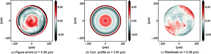
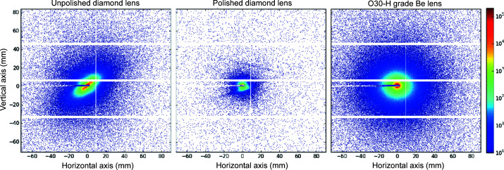
High-quality bi-concave 2D focusing diamond X-ray lenses of apex-radius R = 100 µm produced via laser-ablation and improved via mechanical polishing are presented here. Both for polished and unpolished individual lenses and for stacks of ten lenses, the remaining figure errors determined using X-ray speckle tracking are shown and these results are compared with those of commercial R = 50 µm beryllium lenses that have similar focusing strength and physical aperture. For two stacks of ten diamond lenses (polished and unpolished) and a stack of eleven beryllium lenses, this paper presents measured 2D beam profiles out of focus and wire scans to obtain the beam size in the focal plane. These results are complemented with small-angle X-ray scattering (SAXS) measurements of a polished and an unpolished diamond lens. Again, this is compared with the SAXS of a beryllium lens. The polished X-ray lenses show similar figure errors to commercially available beryllium lenses. While the beam size in the focal plane is comparable to that of the beryllium lenses, the SAXS signal of the polished diamond lenses is considerably lower.

Keywords: X-ray lenses; compound refractive lenses; diamond.


Figures

Figure 1
Figure 1
X-ray white beam topography images. (a) HPHT diamond, (b) single-crystal CVD diamond and (c) CVD diamond plate with lenses cut in it. Diamonds in this image are 3 mm × 3 mm × 0.5 mm in size.
Figure 2
Figure 2
Photograph and sketch of the polishing process (left and middle). On the right, an SEM image shows the diamond lens surface at an interface between a polished and intentionally unpolished region.
Figure 3
Figure 3
Microscope images of an unpolished (left) and a polished (right) lens. The images are taken through the polished side wall of the diamond plate. Both lenses have a physical aperture of A phys ≃ 440 µm.
Figure 4
Figure 4
Packaging of diamond lens: (a) mini v-block for lens ablation, (b) lens support disk containing a diamond with an ablated lens in the middle and fiducial markings indicating azimuthal orientation during the ablation process, (c) lens stacking for an experiment in a commercial lens holder. Lenses are housed in 12 mm-diameter bronze disks.
Figure 5
Figure 5
Laser scanning confocal microscopy of an unpolished diamond lens: (top) 3D reconstruction of front refractive surface, (bottom) residual profile after extraction of a paraboloid fit.
Figure 6
Figure 6
Single-lens radiograph and figure error for each investigated lens type: unpolished R = 100 µm C* lens (top,), polished C* lens (middle) and R = 50 µm Be lens (bottom). Radiographs were taken 800 mm downstream of the sample, enhancing edge effects in phase-contrast imaging (dark rings delimiting the lens geometric aperture).
Figure 7
Figure 7
Dispersion plots of the lenses main figures of merit obtained with XSVT metrology of individual lenses. The OPD is calculated for E = 10 keV.
Figure 8
Figure 8
Lens-stack metrology using XSVT. Top: 10 × unpolished diamond lenses, middle: 10 × polished diamond lenses, bottom: 11 × Be lenses. The coefficients of the polynomial decomposition in (e) are shown in Fig. 9 ▸.
Figure 9
Figure 9
Zernike circle polynomial decomposition of the error profiles in Fig. 8 ▸. The terms Z 1 to Z 4 are suppressed as they account for piston, x and y tilts, and defocus, respectively, and are not strictly optical aberrations. The terms Z 5 and Z 6 represent astigmatism, Z 7 and Z 8 show coma, and Z 9 and Z 10 show tetrafoil aberrations. Z 11 stands for spherical aberration. Z 12 onward are higher-order variations of the aberration terms from Z 5 and Z 11. The orange bars are rotationally symmetric indicating primary to tertiary spherical aberrations.
Figure 10
Figure 10
(a) Measured figure errors of the 10 × polished diamond lens stack. (b) Closest calculated azimuthally symmetric figure error approximation of (a). A phase corrector of inverted thickness variation profile is required to reduce the wavefront aberrations. (c) Calculated residual effective figure errors expected from the combination of the lens stack and phase corrector.
Figure 11
Figure 11
Beam caustics and profiles at the focal plane.
Figure 12
Figure 12
X-ray beam intensity profile as measured 25 mm upstream of focus, at focus, and 25 mm and 50 mm after the focus. Top row: 10 × unpolished diamond lenses. Middle row: 10 × polished diamond lenses. Bottom row: 11 × beryllium lenses. Note that the colour range is different for each column and has been plotted using a power law with exponent 0.33 (gamma correction) in order to highlight less-intense regions.
Figure 13
Figure 13
Beam sizes in the vicinity of the focal plane as measured by scanning a formula image 200 µm tungsten wire through the X-ray beam.
Figure 14
Figure 14
Smallest measured beam size using the wire scan technique for all three lens stacks (top: unpolished C* lenses, middle polished C* lenses, bottom Be lenses). We first take the numerical derivative ΔI diodex of the beam intensity measured via the current generated in a p-i-n photodiode (raw signal: coloured lines with points). This derivative (black dots) is fitted by a Gauss function (solid lines). Left column: horizontal beam size; right column: vertical beam size.
Figure 15
Figure 15
Simulated X-ray beam profile simulated 25 mm upstream of focus, at the image plane, and 25 mm and 50 mm after the focal plane. Top row: 10 × unpolished diamond lenses. Middle row: 10 × polished diamond lenses. Bottom row: 11 × Be lenses. Note the different intensity range for each column. The plots use a gamma correction (γ = 0.33) in order to highlight weaker intensity regions.
Figure 16
Figure 16
Simulated beam sizes (FWHM) in the vicinity of the focal plane for different lens stacks. Horizontal values are represented by lines with black circle markers and the vertical profile sizes by lines with crosses.
Figure 17
Figure 17
Raw 2D detector images showing the SAXS signal of an unpolished (left) and a polished (middle) diamond lens, and an O30-H Be lens (right), taken at a lens-to-detector distance of 8 m with an exposure time of 0.5 s.
Figure 18
Figure 18
1D SAXS intensities for the three investigated lenses compared with the empty background. Note that the raw signal for the unpolished diamond lenses in Fig. 17 ▸ exhibits a large anisotropy. In the azimuthally averaged data a correlation peak appears at q = 0.045 nm−1. Due to the undetermined thickness of the lenses the normalized intensity I(q) is given in steradian−1.
Figure 19
Figure 19
Index of refraction decrement (top) calculated using the xraylib library (Brunetti et al., 2004 ▸) and their ratio (bottom).

References

    1. Alianelli, L., Sawhney, K. J. S., Malik, A., Fox, O. J. L., May, P. W., Stevens, R., Loader, I. M. & Wilson, M. C. (2010). J. Appl. Phys. 108, 123107.
    1. Andrejczuk, A., Krzywiński, J., Sakurai, Y. & Itou, M. (2010). J. Synchrotron Rad. 17, 616–623. - PubMed
    1. Antipov, S., Assoufid, L., Grizolli, W., Qian, J. & Shi, X. (2018). Proceedings of the 9th International Particle Accelerator Conference (IPAC’18), 29 April–4 May 2018, Vancouver, BC, Canada, pp. 4057–4058. THPMF011.
    1. Antipov, S., Baryshev, S. V., Butler, J. E., Antipova, O., Liu, Z. & Stoupin, S. (2016). J. Synchrotron Rad. 23, 163–168. - PMC - PubMed
    1. Artemiev, A., Snigirev, A., Kohn, V., Snigireva, I., Artemiev, N., Grigoriev, M., Peredkov, S., Glikin, L., Levtonov, M., Kvardakov, V., Zabelin, A. & Maevskiy, A. (2006). Rev. Sci. Instrum. 77, 063113.