. 2019 Jul 26;9(40):23229-23240.
doi: 10.1039/c9ra03761f. eCollection 2019 Jul 23.

Effects of wall velocity slip on droplet generation in microfluidic T-junctions

Affiliations

Effects of wall velocity slip on droplet generation in microfluidic T-junctions

Xinlong Li et al. RSC Adv. .

Abstract

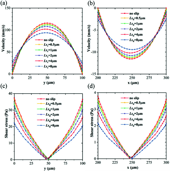
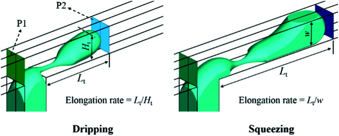
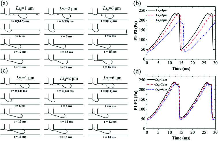
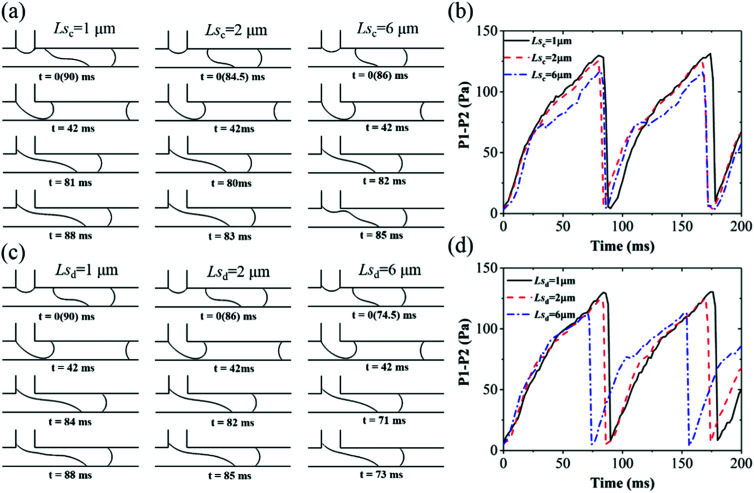
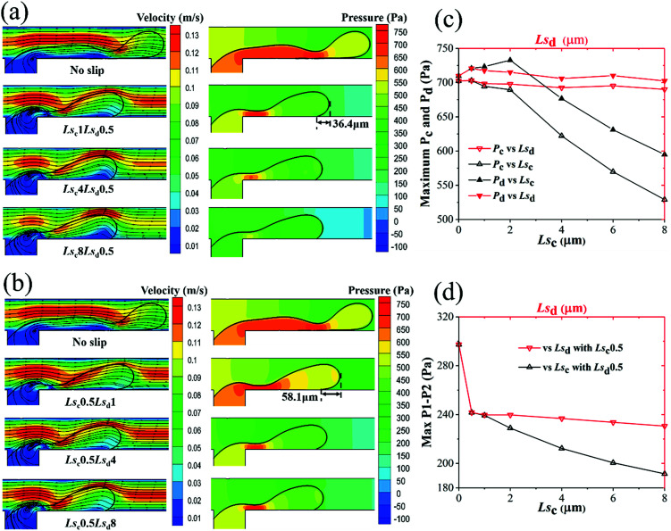
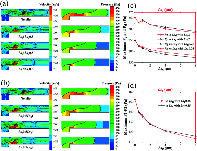
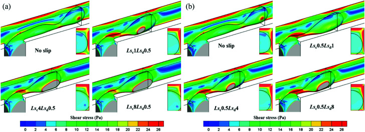
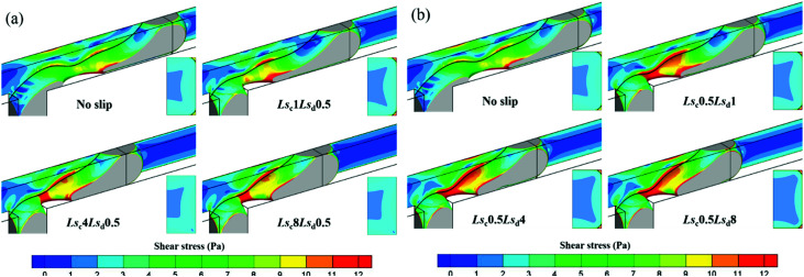
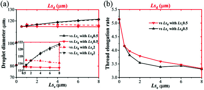
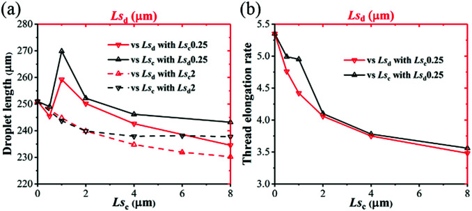
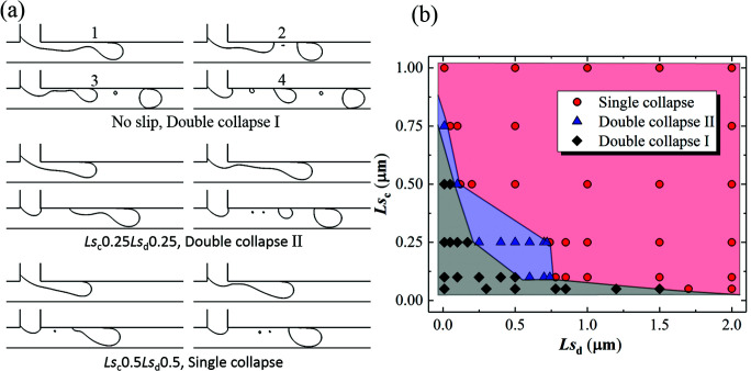
The effect of the slip lengths of both continuous and dispersed phases on droplet formation in microfluidic T-junctions is investigated by a volume of fluid method. Results reveal that, in a dripping regime, the droplet size is mainly influenced by the slip length of the continuous phase and increases with it. In a squeezing regime, the droplet size decreases with the slip lengths of both phases. The effects of the slip lengths of both phases on droplet generation are systematically discussed and summarized. The elongation rate of the thread can be decreased with an increase of slip lengths in both dripping and squeezing regimes, which is beneficial to improve droplet monodispersity. The monodispersity of droplets can deteriorate when the slip length of either phase is small and can be improved by increasing the slip length of the other phase.


Conflict of interest statement

There are no conflicts to declare.

Figures

Fig. 1
Fig. 1. Dispersed phase and continuous phase in contact with the solid wall for different contact angles and a local enlarged view of the contact area of the liquid and solid wall.
Fig. 2
Fig. 2. T-junction microchannel geometry for simulation and a sketch of wall velocity slip.
Fig. 3
Fig. 3. Grid independence study for Qd = 0.2 mL h−1 and Qc = 2 mL h−1 with moderate slip lengths of 2 μm. Ux1 and Ux2 represent the x-velocity along the y-direction at x = 100 μm and x = 150 μm on the symmetry plane, respectively.
Fig. 4
Fig. 4. (a) Geometry of the microchannel for slip model validation. (b) Velocity profiles from experiment and simulation along the line of x = 300 μm and z = 15 μm; the x-axis is the velocity normalized by the free stream velocity and the y-axis is the distance from the wall.
Fig. 5
Fig. 5. Validation with the experiments of (a) van der Graaf et al. and (b) Garstecki et al. (c) Snapshots of (I) experiments and (II) our simulations with Qc = 2 mL h−1, Lsc = 0.5 μm, Lsd = 2 μm. (d) Snapshots of experiments (left) and our simulations (right) with Lsc = 1 μm and Lsd = 0.1 μm for (I) Qd = 0.004 μL s−1, Qc = 0.028 μL s−1; (II) Qd = 0.14 μL s−1, Qc = 0.139 μL s−1; (III) Qd = 0.05 μL s−1, Qc = 0.028 μL s−1.
Fig. 6
Fig. 6. Velocity distribution at (a) line x = 150 μm along y-direction and (b) line y = 200 μm along the x-direction on the symmetry plane for different Lsc and Lsd with Qd = 0.2 mL h−1 and Qc = 2 mL h−1; (c) and (d) represent resistant shear stresses exerted by the slow object (adjacent fluid or wall) corresponding to (a) and (b).
Fig. 7
Fig. 7. Generating a droplet in a dripping regime and squeezing regime.
Fig. 8
Fig. 8. Dripping regime with Qd = 0.2 mL h−1 and Qc = 2 mL h−1. (a) Droplet generation process and (b) pressure drop through the thread with time under different Lsc with Lsd = 0.5 μm. (c) Droplet generation process and (d) pressure drop through the thread with time under different Lsd with Lsc = 0.5 μm.
Fig. 9
Fig. 9. Squeezing regime with Qd = 0.09 mL h−1 and Qc = 0.18 mL h−1. (a) Droplet generation process and (b) pressure drop through the thread with time under different Lsc with Lsd = 0.5 μm. (c) Droplet generation process and (d) pressure drop through the thread with time under different Lsd with Lsc = 0.5 μm.
Fig. 10
Fig. 10. Velocity contours with streamlines and pressure contours of (a) different Lsc with Lsd = 0.5 μm and (b) different Lsd with Lsc = 0.5 μm. (c) Maximum pressure at continuous and dispersed phase inlets and (d) maximum pressure drop across the thread as functions of Lsc and Lsd in a dripping regime with Qd = 0.2 mL h−1 and Qc = 2 mL h−1.
Fig. 11
Fig. 11. Velocity contours with streamlines and pressure contours of (a) different Lsc when Lsd = 0.5 μm and (b) different Lsd when Lsc = 0.5 μm. (c) Maximum pressure on continuous and dispersed phase inlets and (d) maximum pressure drop across the thread as functions of Lsc and Lsd in dripping regime with Qd = 0.09 mL h−1 and Qc = 0.18 mL h−1.
Fig. 12
Fig. 12. Droplet surface colored by shear stress magnitude with (a) different Lsc when Lsd = 0.5 μm and (b) different Lsd when Lsc = 0.5 μm for Qd = 0.2 mL h−1 and Qc = 2 mL h−1 in a dripping regime.
Fig. 13
Fig. 13. Droplet surface colored by shear stress magnitude with (a) different Lsc when Lsd = 0.5 μm and (b) different Lsd when Lsc = 0.5 μm for Qd = 0.09 mL h−1 and Qc = 0.18 mL h−1 in a squeezing regime.
Fig. 14
Fig. 14. (a) Droplet diameter and (b) thread elongation rate as functions of Lsc and Lsd in a dripping regime with Qd = 0.2 mL h−1 and Qc = 2 mL h−1.
Fig. 15
Fig. 15. (a) Droplet length and (b) thread elongation rate as functions of Lsc and Lsd in a squeezing regime with Qd = 0.09 mL h−1 and Qc = 0.18 mL h−1.
Fig. 16
Fig. 16. (a) Three different droplet generation states and (b) phase diagram of droplet generation state as a function of Lsc and Lsd in a dripping regime with Qd = 0.2 mL h−1and Qc = 2 mL h−1.

Similar articles

References

    1. Song H. Chen D. L. Ismagilov R. F. Angew. Chem., Int. Ed. 2006;45:7336–7356. doi: 10.1002/anie.200601554. - DOI - PMC - PubMed
    1. Kaminski T. S. Garstecki P. Chem. Soc. Rev. 2017;46:6210–6226. doi: 10.1039/C5CS00717H. - DOI - PubMed
    1. Hoang P. H. Yoon K.-B. Kim D.-P. RSC Adv. 2012;2:5323–5328. doi: 10.1039/C2RA20074K. - DOI
    1. Avesar J. Ben Arye T. Levenberg S. Lab Chip. 2014;14:2161–2167. doi: 10.1039/C4LC00013G. - DOI - PubMed
    1. Li Y. Yan L. Liu Y. Qian K. Liu B. Yang P. Liu B. RSC Adv. 2015;5:1331–1342. doi: 10.1039/C4RA12333F. - DOI