Review
. 2020 Nov 13;10(68):41625-41679.
doi: 10.1039/d0ra07931f. eCollection 2020 Nov 11.

Widely used catalysts in biodiesel production: a review

Affiliations
Review

Widely used catalysts in biodiesel production: a review

Bishwajit Changmai et al. RSC Adv. .

Abstract

An ever-increasing energy demand and environmental problems associated with exhaustible fossil fuels have led to the search for an alternative renewable source of energy. In this context, biodiesel has attracted attention worldwide as an eco-friendly alternative to fossil fuel for being renewable, non-toxic, biodegradable, and carbon-neutral. Although the homogeneous catalyst has its own merits, much attention is currently paid toward the chemical synthesis of heterogeneous catalysts for biodiesel production as it can be tuned as per specific requirement and easily recovered, thus enhancing reusability. Recently, biomass-derived heterogeneous catalysts have risen to the forefront of biodiesel productions because of their sustainable, economical and eco-friendly nature. Furthermore, nano and bifunctional catalysts have emerged as a powerful catalyst largely due to their high surface area, and potential to convert free fatty acids and triglycerides to biodiesel, respectively. This review highlights the latest synthesis routes of various types of catalysts (including acidic, basic, bifunctional and nanocatalysts) derived from different chemicals, as well as biomass. In addition, the impacts of different methods of preparation of catalysts on the yield of biodiesel are also discussed in details.


Conflict of interest statement

There are no conflicts to declare.

Figures

Fig. 1
Fig. 1. Publications per year for biodiesel during the period 1993 to Feb 2020 (data collected from SciFinder Database).
Scheme 1
Scheme 1. Base-catalyzed reaction mechanism for the transesterification of TGs of vegetable oil to biodiesel.
Scheme 2
Scheme 2. Acid-catalyzed esterification of FFA content of vegetable oil to biodiesel.
Fig. 2
Fig. 2. Catalyst classification for biodiesel synthesis.
Fig. 3
Fig. 3. Schematic portrayal of experimental set up for the ultrasonic-assisted transesterification reaction. Reproduced from ref. 86.
Fig. 4
Fig. 4. SEM image (A) and FT-IR spectrum (B and C) of Mn-doped ZnO nanomaterial. Reproduced from ref. 92.
Fig. 5
Fig. 5. SEM micrographs of (a) Hβ and (b) 30% SiW12/Hβ. Reproduced from ref. 101.
Fig. 6
Fig. 6. XRD pattern of pure zeolite (a), La2O3/NaY-600 (b), La2O3/NaY-800 (c), S–La2O3/NaY-800 (d), La2O3/NaY-1000 (e). Reproduced from ref. 105.
Fig. 7
Fig. 7. RPB experimental apparatus utilized for the heterogeneously catalyzed transesterification reaction. Components: (1) CSTR reactor; (2) stirrer; (3) thermocouples; (4) sample port; (5) thermostat; (6) control valve; (7) pumps; (8) flow-meter; (9) RPB reactor; (10) stationary liquid distributor; (11) packed-bed rotator; (12) K/g-Al2O3 catalyst; (13) housing case; (14) rotor shaft; (15) motor. Reproduced from ref. 111.
Fig. 8
Fig. 8. Schematic diagram of PBMR for FAME synthesis. Components: (1) palm oil; (2) methanol; (3) crude material siphon; (4) magnetic stirrer; (5) blending vessel; (6) flowing siphon; (7) boiling water flowing; (8) water chiller; (9) wound thermal exchanger; (10) ceramic membrane; (11) pressure check; (12) temperature indicator; (13) methanol recuperation unit; (14) siphon; (15) isolating funnel. Reproduced from ref. 122.
Fig. 9
Fig. 9. SEM image of KF/Ca–Al. Reproduced from ref. 138.
Fig. 10
Fig. 10. SEM image of Mg–Al HT calcined at 850 °C. Reproduced from ref. 140.
Fig. 11
Fig. 11. Proposed model for the solid-state reaction on the catalyst surface. Reproduced from ref. 145.
Scheme 3
Scheme 3. Proposed models for CaCO3 decomposition to CaO (A) and mixed precipitate of Ca–Zn (B). Reproduced from ref. 150.
Fig. 12
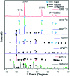
Fig. 12. XRD patterns of natural eggshell and the materials obtained by calcining natural eggshell in the range of 200–1000 °C. Reproduced from ref. 161.
Fig. 13
Fig. 13. SEM image of (a) eggshell-CaO-900 and (b) eggshell-CaO-900-600. Reproduced from ref. 172.
Fig. 14
Fig. 14. Microwave-assisted synthesis of FAME using an eggshell catalyst. Reproduced from ref. 190.
Fig. 15
Fig. 15. Flow diagram of biodiesel production utilizing chicken eggshell catalyst. Reproduced from ref. 190.
Fig. 16
Fig. 16. Schematic layout for eggshell-originated CaO synthesis. Reproduced from ref. 192.
Fig. 17
Fig. 17. TEM images and particle size distributions of the surfactant assistant CaO nanocatalysts: after 40 min (a), after 80 min (b), and after 120 min (c). CO2 desorption performance commercial of CaO (a), and nano CaO catalysts: after 40 min (b), after 80 min (c), and after 120 min (d). Reproduced from ref. 202.
Fig. 18
Fig. 18. XRD spectra of normal and calcined (400–1000 °C) snail shells. Reproduced from ref. 228.
Fig. 19
Fig. 19. Flowchart for the synthesis of ash catalyst derived from plant biomass.
Fig. 20
Fig. 20. SEM micrograph of palm ash. Reproduced from ref. 264.
Fig. 21
Fig. 21. XRD patterns of calcined coconut husk calcined at different temperatures. Reproduced from ref. 268.
Fig. 22
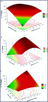
Fig. 22. 3-D plots of biodiesel yield. (a) Impact of M/O molar ratio and catalyst loading, (b) reaction time and catalyst loading, and (c) M/O molar ratio and reaction time on the biodiesel yield. Reproduced from ref. 272.
Fig. 23
Fig. 23. 1H NMR spectrum of (a) WCO and (b) Biodiesel. Reproduced from ref. 274.
Fig. 24
Fig. 24. XPS survey (a), C 1s (b), O 1s (c), and K 2p (d) spectra of MAPA. Reproduced from ref. 275.
Fig. 25
Fig. 25. EDS images of (a) uncalcined and (b) calcined banana peduncle. Reproduced from ref. 279.
Fig. 26
Fig. 26. GC-MS spectrum of biodiesel from soybean oil. Reproduced from ref. 282.
Fig. 27
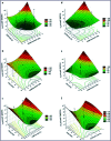
Fig. 27. Contour and surface plots for PKOME synthesis. Reproduced from ref. 290.
Fig. 28
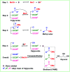
Fig. 28. Synthesis of sulfonated carbon catalyst from sucrose and d-glucose. Reproduced from ref. 364.
Fig. 29
Fig. 29. FT-IR (a) and 13C MAS NMR (b) spectra for the sulfonated carbon catalyst originated from cellulose. Reproduced from ref. 368.
Fig. 30
Fig. 30. Schematic structures of the SO3H-bearing CCSA materials carbonized at below 723 K (A) and above 823 K (B). Reproduced from ref. 365.
Fig. 31
Fig. 31. Schematic representation of transesterification of various oils using activated carbon-based catalysts.
Fig. 32
Fig. 32. FESEM images of (a) C and (b) C–SO3H. Reproduced from ref. 378.
Fig. 33
Fig. 33. TEM micrograph for Cu/Zn(10 : 90)/γ-Al2O3-800 °C (a). The HRTEM images displayed the lattice fringes of (b) Al2O3 (400), (c) Al2O3 (220), (d) Al2O3 (311), (e) CuO (200) and (f) ZnO (100). Reproduced from ref. 431.
Fig. 34
Fig. 34. Schematic diagram of a high-temperature reactor. Reproduced from ref. 437.
Fig. 35
Fig. 35. TEM image of HPA-ZIF-8. Reproduced from ref. 439.
Fig. 36
Fig. 36. Representative diagram for biodiesel production. Reproduced from ref. 447.

Similar articles

Cited by

References

    1. Ciarrocchi G. Montecucco A. Pedrali-Noy G. Spadari S. Biochem. Pharmacol. 1988;37:1803–1804. doi: 10.1016/0006-2952(88)90454-6. - DOI - PubMed
    1. Yin X. Duan X. You Q. Dai C. Tan Z. Zhu X. Energy Convers. Manage. 2016;112:199–207. doi: 10.1016/j.enconman.2016.01.026. - DOI
    1. International Renewable Energy Agency (IRENA), Global Energy Transformation: A Roadmap to 2050, 2018
    1. IEA, Int. Energy Agency, Peris, 2016, pp. 1–77
    1. Kulkarni M. G. Dalai A. K. Ind. Eng. Chem. Res. 2006;45:2901–2913. doi: 10.1021/ie0510526. - DOI