

Enhanced inertial focusing of microparticles and cells by integrating trapezoidal microchambers in spiral microfluidic channels
- PMID: 35516901
- PMCID: PMC9064905
- DOI: 10.1039/c9ra03587g
Enhanced inertial focusing of microparticles and cells by integrating trapezoidal microchambers in spiral microfluidic channels
Abstract
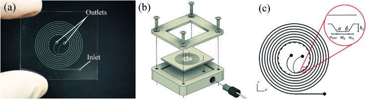
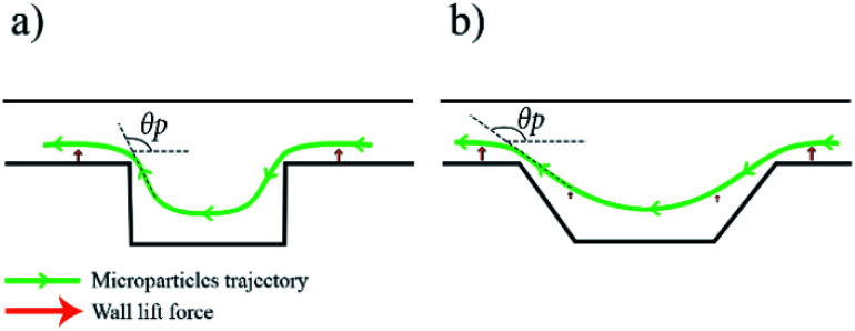
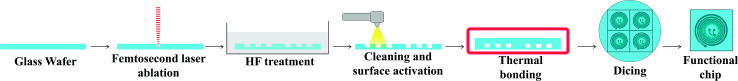
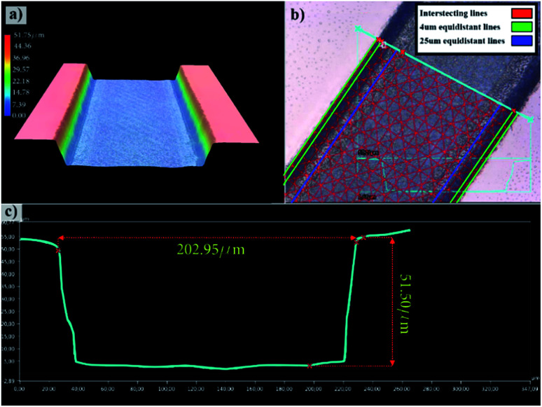
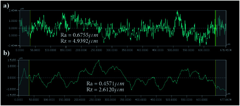
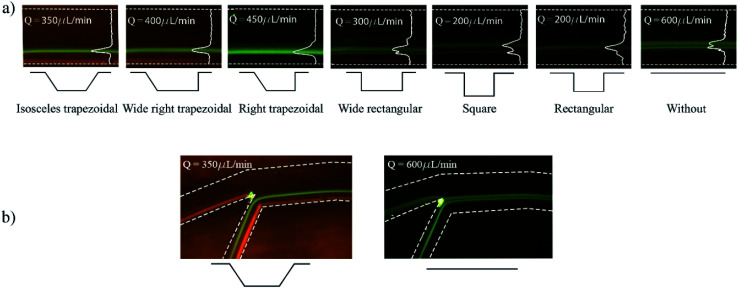
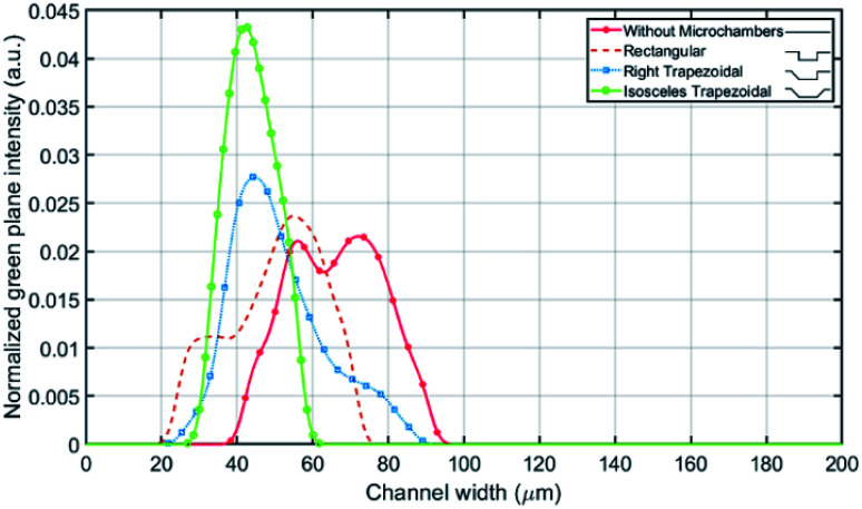
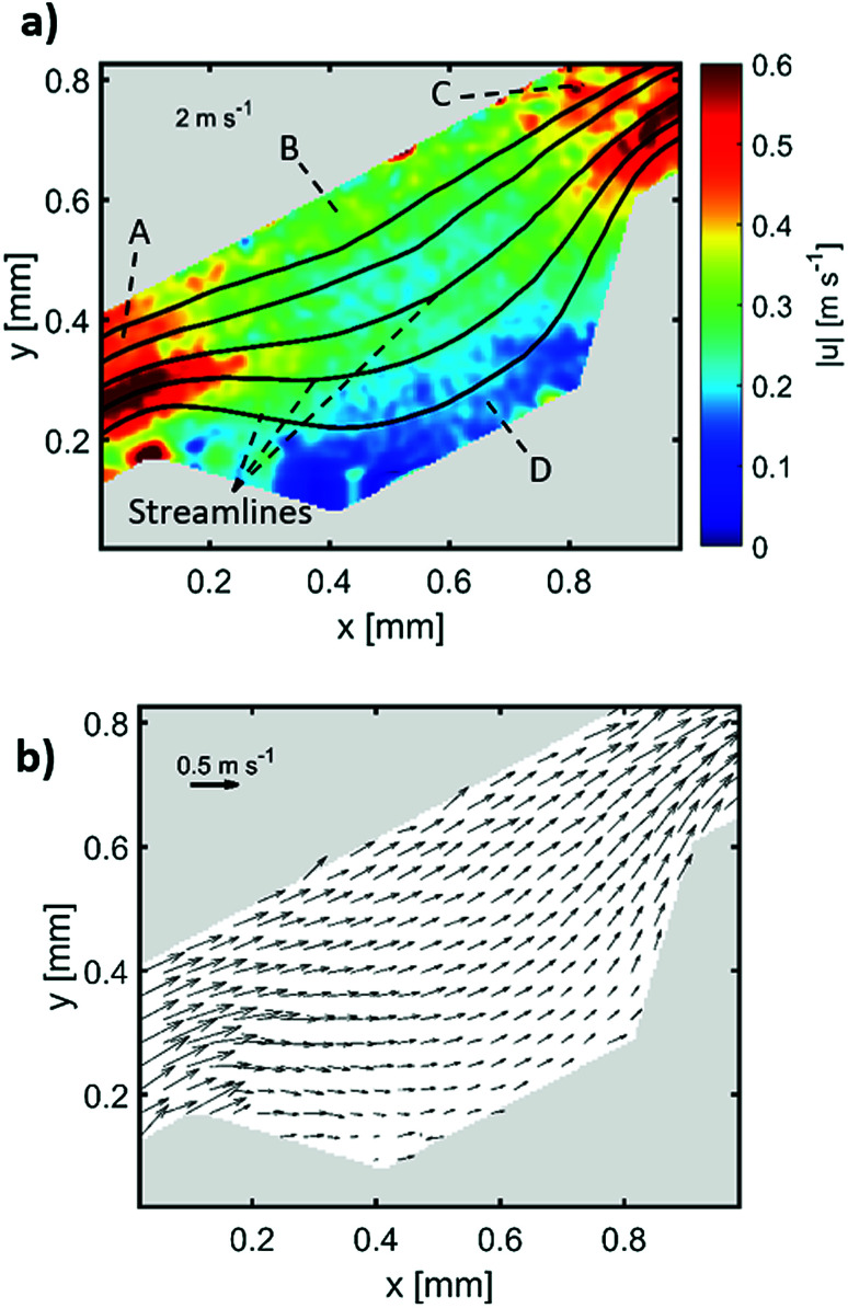
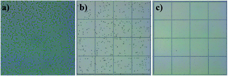
In this work, manipulating width and equilibrium position of fluorescent microparticles in spiral microchannel fractionation devices by embedding microchambers along the last turn of a spiral is reported. Microchambers with different shapes and sizes were tested at Reynolds numbers between 15.7 and 156.6 (100-1000 μL min-1) to observe focusing of 2, 5 and 10 μm fluorescent microparticles. This paper also discusses the fabrication process of the microfluidic chips with femtosecond laser ablation on glass wafers, as well as a particle imaging velocimetry (μPIV) study of microparticle trajectories inside a microchamber. It could be demonstrated with an improved final design with inclined microchamber side walls, that the 2 μm particle equilibrium position is shifted towards the inner wall by ∼27 μm and the focusing line's width is reduced by ∼18 μm. Finally, Saccharomyces cerevisiae yeast cells were tested in the final chip and a cell focusing efficiency of 99.1% is achieved.
This journal is © The Royal Society of Chemistry.
Conflict of interest statement
There are no conflicts to declare.
Figures
Similar articles
-
High-Efficiency Small Sample Microparticle Fractionation on a Femtosecond Laser-Machined Microfluidic Disc.Micromachines (Basel). 2020 Jan 30;11(2):151. doi: 10.3390/mi11020151. Micromachines (Basel). 2020. PMID: 32019235 Free PMC article.
-
Sheath-less high throughput inertial separation of small microparticles in spiral microchannels with trapezoidal cross-section.RSC Adv. 2019 Dec 18;9(71):41970-41976. doi: 10.1039/c9ra05916d. eCollection 2019 Dec 13. RSC Adv. 2019. PMID: 35541623 Free PMC article.
-
Spiral Microchannels with Trapezoidal Cross Section Fabricated by Femtosecond Laser Ablation in Glass for the Inertial Separation of Microparticles.Micromachines (Basel). 2018 Apr 9;9(4):171. doi: 10.3390/mi9040171. Micromachines (Basel). 2018. PMID: 30424104 Free PMC article.
-
Picosecond Laser Etching of Glass Spiral Microfluidic Channel for Microparticles Dispersion and Sorting.Micromachines (Basel). 2025 Jan 7;16(1):66. doi: 10.3390/mi16010066. Micromachines (Basel). 2025. PMID: 39858721 Free PMC article.
-
Continuous focusing of microparticles using inertial lift force and vorticity via multi-orifice microfluidic channels.Lab Chip. 2009 Apr 7;9(7):939-48. doi: 10.1039/b813952k. Epub 2008 Dec 12. Lab Chip. 2009. PMID: 19294305
Cited by
-
A Continuous Microfluidic Concentrator for High-Sensitivity Detection of Bacteria in Water Sources.Micromachines (Basel). 2022 Jul 10;13(7):1093. doi: 10.3390/mi13071093. Micromachines (Basel). 2022. PMID: 35888910 Free PMC article.
-
High-Efficiency Small Sample Microparticle Fractionation on a Femtosecond Laser-Machined Microfluidic Disc.Micromachines (Basel). 2020 Jan 30;11(2):151. doi: 10.3390/mi11020151. Micromachines (Basel). 2020. PMID: 32019235 Free PMC article.
-
Accelerated Particle Separation in a DLD Device at Re > 1 Investigated by Means of µPIV.Micromachines (Basel). 2019 Nov 11;10(11):768. doi: 10.3390/mi10110768. Micromachines (Basel). 2019. PMID: 31718021 Free PMC article.
-
Sheath-less high throughput inertial separation of small microparticles in spiral microchannels with trapezoidal cross-section.RSC Adv. 2019 Dec 18;9(71):41970-41976. doi: 10.1039/c9ra05916d. eCollection 2019 Dec 13. RSC Adv. 2019. PMID: 35541623 Free PMC article.
-
Parallelization of Curved Inertial Microfluidic Channels to Increase the Throughput of Simultaneous Microparticle Separation and Washing.Micromachines (Basel). 2024 Sep 30;15(10):1228. doi: 10.3390/mi15101228. Micromachines (Basel). 2024. PMID: 39459102 Free PMC article.
References
LinkOut - more resources
Full Text Sources
Miscellaneous