

Graphene/Si Schottky solar cells: a review of recent advances and prospects
- PMID: 35517633
- PMCID: PMC9059660
- DOI: 10.1039/c8ra08035f
Graphene/Si Schottky solar cells: a review of recent advances and prospects
Abstract
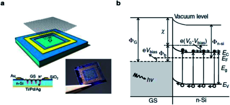
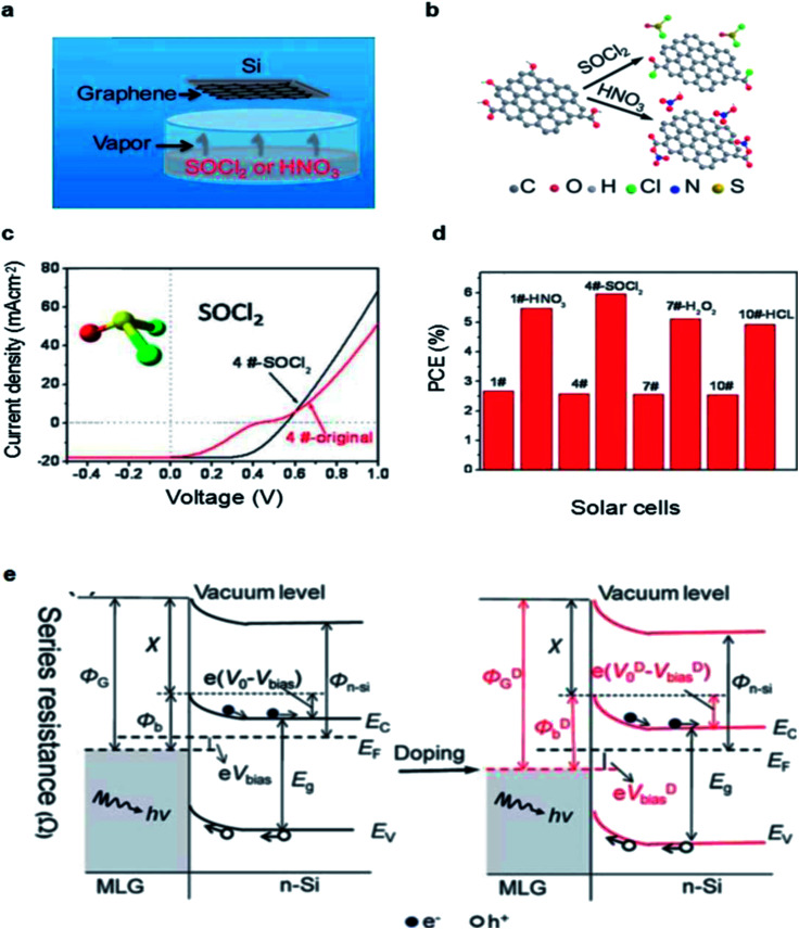
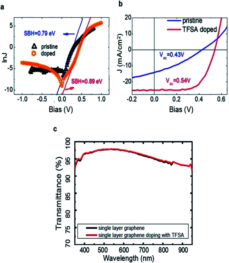
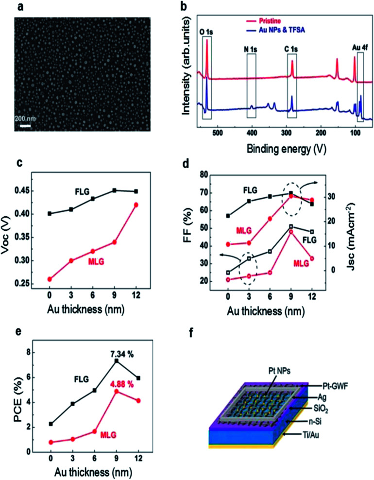
Graphene has attracted tremendous interest due to its unique physical and chemical properties. The atomic thickness, high carrier mobility and transparency make graphene an ideal electrode material which can be applied to various optoelectronic devices such as solar cells, light-emitting diodes and photodetectors. In recent years, there has been a growing interest in developing graphene/silicon Schottky junction solar cells and the power conversion efficiency has reached up to 15.8% with an incredible speed. In this review, we introduce the structure and mechanism of graphene/silicon solar cells briefly, and then summarize several key strategies to improve the performance of the cells. Finally, the challenges and prospects of graphene/silicon solar cells are discussed in the development of the devices in detail.
This journal is © The Royal Society of Chemistry.
Conflict of interest statement
There are no conflicts to declare.
Figures
Similar articles
-
Interface engineering of graphene-silicon Schottky junction solar cells with an Al2O3 interfacial layer grown by atomic layer deposition.RSC Adv. 2018 Mar 16;8(19):10593-10597. doi: 10.1039/c7ra13443f. eCollection 2018 Mar 13. RSC Adv. 2018. PMID: 35540487 Free PMC article.
-
Functionalized graphene and other two-dimensional materials for photovoltaic devices: device design and processing.Chem Soc Rev. 2015 Aug 7;44(15):5638-79. doi: 10.1039/c4cs00455h. Epub 2015 May 29. Chem Soc Rev. 2015. PMID: 26024242
-
High-performance single CdS nanowire (nanobelt) Schottky junction solar cells with Au/graphene Schottky electrodes.ACS Appl Mater Interfaces. 2010 Dec;2(12):3406-10. doi: 10.1021/am1007672. Epub 2010 Nov 8. ACS Appl Mater Interfaces. 2010. PMID: 21058686
-
Advances in solar energy harvesting integrated by van der Waals graphene heterojunctions.RSC Adv. 2023 Oct 27;13(44):31273-31291. doi: 10.1039/d3ra06016k. eCollection 2023 Oct 18. RSC Adv. 2023. PMID: 37901851 Free PMC article. Review.
-
The Impact of Graphene on the Fabrication of Thin Film Solar Cells: Current Status and Future Prospects.Materials (Basel). 2017 Dec 27;11(1):36. doi: 10.3390/ma11010036. Materials (Basel). 2017. PMID: 29280964 Free PMC article. Review.
Cited by
-
Graphene Oxide Layer-by-Layer Films for Sensors and Devices.Nanomaterials (Basel). 2021 Jun 12;11(6):1556. doi: 10.3390/nano11061556. Nanomaterials (Basel). 2021. PMID: 34204721 Free PMC article.
-
Graphene/Semiconductor Heterostructure Wireless Energy Harvester through Hot Electron Excitation.Research (Wash D C). 2020 Jun 8;2020:3850389. doi: 10.34133/2020/3850389. eCollection 2020. Research (Wash D C). 2020. PMID: 32566930 Free PMC article.
-
The Graphene Structure's Effects on the Current-Voltage and Photovoltaic Characteristics of Directly Synthesized Graphene/n-Si(100) Diodes.Nanomaterials (Basel). 2022 May 11;12(10):1640. doi: 10.3390/nano12101640. Nanomaterials (Basel). 2022. PMID: 35630863 Free PMC article.
-
Nanographene horizons: the emerging role of hexa-peri-hexabenzocoronene in functional material design.RSC Adv. 2025 Aug 27;15(37):30490-30551. doi: 10.1039/d5ra04623h. eCollection 2025 Aug 22. RSC Adv. 2025. PMID: 40895744 Free PMC article. Review.
-
Inverted perovskite solar cells with enhanced lifetime and thermal stability enabled by a metallic tantalum disulfide buffer layer.Nanoscale Adv. 2021 Apr 9;3(11):3124-3135. doi: 10.1039/d1na00172h. eCollection 2021 Jun 1. Nanoscale Adv. 2021. PMID: 36133666 Free PMC article.
References
-
- Green M. A. Energy Policy. 2000;28:989–998. doi: 10.1016/S0301-4215(00)00086-0. - DOI
-
- Ashraf S. Su R. Akhtar J. Siddiqi H. M. El-Shafei A. Dyes Pigm. 2018;150:347–353. doi: 10.1016/j.dyepig.2017.12.035. - DOI
-
- Yoshikawa K. Yoshida W. Irie T. Kawasaki H. Konishi K. Ishibashi H. Asatani T. Adachi D. Kanematsu M. Uzu H. Yamamoto K. Sol. Energy Mater. Sol. Cells. 2017;173:37–42. doi: 10.1016/j.solmat.2017.06.024. - DOI
Publication types
LinkOut - more resources
Full Text Sources