

Axial motion estimation and correction for simultaneous multi-plane two-photon calcium imaging
- PMID: 35519241
- PMCID: PMC9045928
- DOI: 10.1364/BOE.445775
Axial motion estimation and correction for simultaneous multi-plane two-photon calcium imaging
Abstract
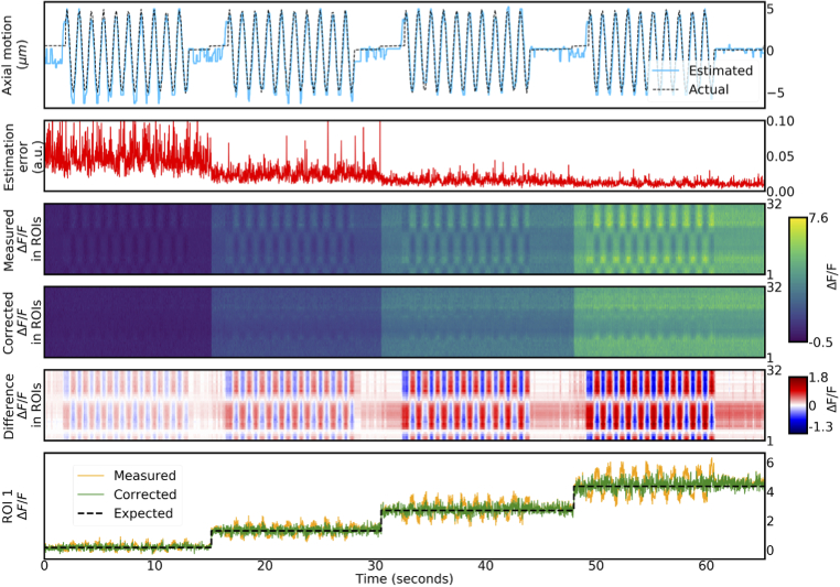
Two-photon imaging in behaving animals is typically accompanied by brain motion. For functional imaging experiments, for example with genetically encoded calcium indicators, such brain motion induces changes in fluorescence intensity. These motion-related intensity changes or motion artifacts can typically not be separated from neural activity-induced signals. While lateral motion, within the focal plane, can be corrected by computationally aligning images, axial motion, out of the focal plane, cannot easily be corrected. Here, we developed an algorithm for axial motion correction for non-ratiometric calcium indicators taking advantage of simultaneous multi-plane imaging. Using temporally multiplexed beams, recording simultaneously from at least two focal planes at different z positions, and recording a z-stack for each beam as a calibration step, the algorithm separates motion-related and neural activity-induced changes in fluorescence intensity. The algorithm is based on a maximum likelihood optimisation approach; it assumes (as a first order approximation) that no distortions of the sample occurs during axial motion and that neural activity increases uniformly along the optical axis in each region of interest. The developed motion correction approach allows axial motion estimation and correction at high frame rates for isolated structures in the imaging volume in vivo, such as sparse expression patterns in the fruit fly brain.
© 2022 Optica Publishing Group under the terms of the Optica Open Access Publishing Agreement.
Conflict of interest statement
The authors declare that there are no conflicts of interest related to this article.
Figures


Similar articles
-
Correction of z-motion artefacts to allow population imaging of synaptic activity in behaving mice.J Physiol. 2020 May;598(10):1809-1827. doi: 10.1113/JP278957. Epub 2020 Mar 3. J Physiol. 2020. PMID: 32020615 Free PMC article.
-
Particle Tracking Facilitates Real Time Capable Motion Correction in 2D or 3D Two-Photon Imaging of Neuronal Activity.Front Neural Circuits. 2017 Aug 15;11:56. doi: 10.3389/fncir.2017.00056. eCollection 2017. Front Neural Circuits. 2017. PMID: 28860973 Free PMC article.
-
Recording Neural Activity in Unrestrained Animals with Three-Dimensional Tracking Two-Photon Microscopy.Cell Rep. 2018 Oct 30;25(5):1371-1383.e10. doi: 10.1016/j.celrep.2018.10.013. Cell Rep. 2018. PMID: 30380425 Free PMC article.
-
Fast and Accurate Motion Correction for Two-Photon Ca2+ Imaging in Behaving Mice.Front Neuroinform. 2022 Apr 26;16:851188. doi: 10.3389/fninf.2022.851188. eCollection 2022. Front Neuroinform. 2022. PMID: 35559212 Free PMC article.
-
Monitoring activity in neural circuits with genetically encoded indicators.Front Mol Neurosci. 2014 Dec 5;7:97. doi: 10.3389/fnmol.2014.00097. eCollection 2014. Front Mol Neurosci. 2014. PMID: 25538558 Free PMC article. Review.
Cited by
-
Deep-brain optical recording of neural dynamics during behavior.Neuron. 2023 Dec 6;111(23):3716-3738. doi: 10.1016/j.neuron.2023.09.006. Epub 2023 Oct 6. Neuron. 2023. PMID: 37804833 Free PMC article. Review.
-
Removing crosstalk signals in neuron activity by time multiplexed excitations in a two-photon all-optical physiology system.Biomed Opt Express. 2024 Mar 29;15(4):2708-2718. doi: 10.1364/BOE.521047. eCollection 2024 Apr 1. Biomed Opt Express. 2024. PMID: 38633062 Free PMC article.
-
Dynamics of glia and neurons regulate homeostatic rest, sleep and feeding behavior in Drosophila.Nat Neurosci. 2025 Jun;28(6):1226-1240. doi: 10.1038/s41593-025-01942-1. Epub 2025 Apr 21. Nat Neurosci. 2025. PMID: 40259071 Free PMC article.
-
Rapid, high-contrast, and steady volumetric imaging with Bessel-beam-based two-photon fluorescence microscopy.J Biomed Opt. 2024 Jan;29(1):016501. doi: 10.1117/1.JBO.29.1.016501. Epub 2024 Jan 24. J Biomed Opt. 2024. PMID: 38269082 Free PMC article.
References
-
- Griffiths V. A., Valera A. M., Lau J. Y., Roš H., Younts T. J., Marin B., Baragli C., Coyle D., Evans G. J., Konstantinou G., Koimtzis T., Nadella K. M. N. S., Punde S. A., Kirkby P. A., Bianco I. H., Silver R. A., “Real-time 3d movement correction for two-photon imaging in behaving animals,” Nat. Methods 17(7), 741–748 (2020).10.1038/s41592-020-0851-7 - DOI - PMC - PubMed
LinkOut - more resources
Full Text Sources