

Improving the size uniformity of dendritic fibrous nano-silica by a facile one-pot rotating hydrothermal approach
- PMID: 35528672
- PMCID: PMC9069929
- DOI: 10.1039/c9ra04845f
Improving the size uniformity of dendritic fibrous nano-silica by a facile one-pot rotating hydrothermal approach
Abstract
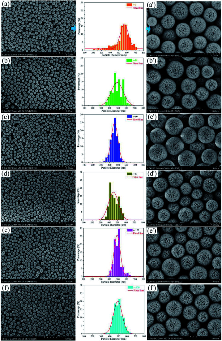
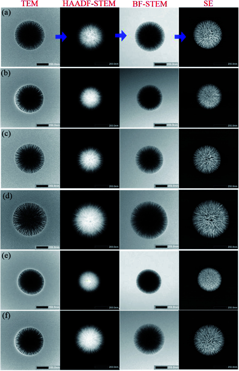
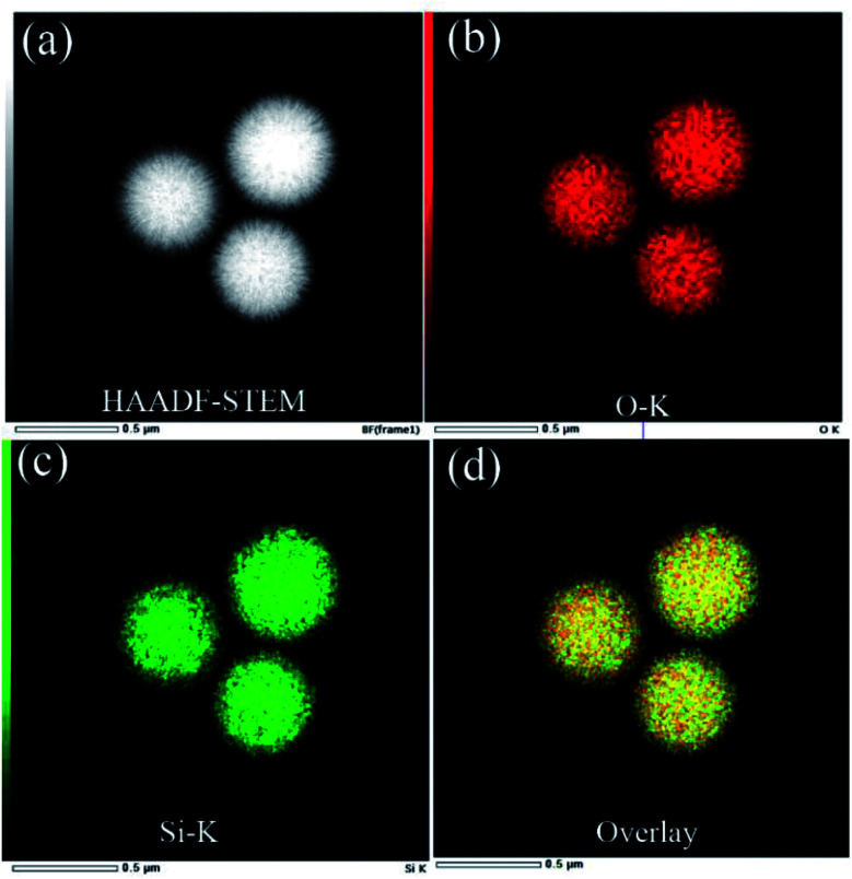
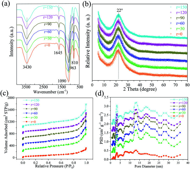
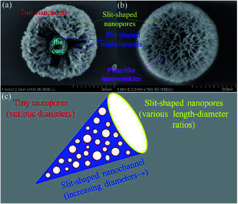
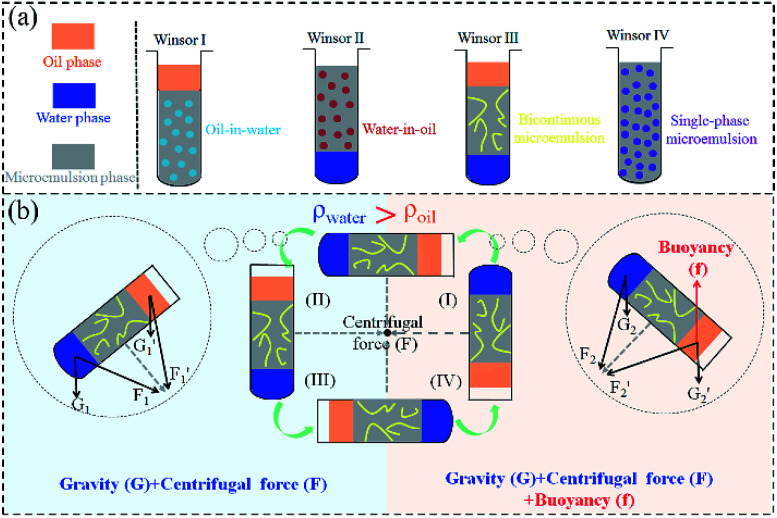
Dendritic fibrous nano-silica (DFNS), also well-known as KCC-1, possesses three-dimensional center-radial nanochannels and hierarchical nanopores. Compared with conventional mesoporous materials like SBA-15, these special structural characteristics endow DFNS with more accessible internal space, higher specific surface area, larger pore volume, etc. Even though great progress has been achieved, the as-prepared KCC-1 nanospheres exhibit extremely non-uniform diameters and their sizes differ enormously in almost all available traditional synthesis approaches. Herein, a facile and low-cost one-pot rotating hydrothermal approach is adopted to improve the size uniformity of dendritic fibrous nano-silica. Stirring rates of 30, 60, 90, 120, and 150 (the maximum) revolutions per minute (rpm) can influence KCC-1 uniformity to certain extents. Among them, 60 rpm can be considered to be an ideal stirring rate for relatively uniform KCC-1 because of the best sufficient contact of reaction phases. A plausible synthesis mechanism can be explained in terms of continuously variable stress conditions of the reaction mother liquor (i.e., the bicontinuous microemulsion) during the fabrication process. To be specific, except for gravity (G), this technique brings about the centrifugal force (F) stemming from the stirring rate, and the buoyancy (f) originated from vigorous reversal of organic phase in the reaction solution. These forces synergistically mix organic phase and water phase, which generates new bicontinuous microemulsion droplets (BMDs) to supplement the consumed ones. All in all, this approach as well as the synthesis equipment is simple, inexpensive, and reproducible for large-scale KCC-1 preparation with improved size uniformity.
This journal is © The Royal Society of Chemistry.
Conflict of interest statement
There are no conflicts to declare.
Figures
References
LinkOut - more resources
Full Text Sources