

T-shaped double-strip spoof surface plasmon polariton transmission lines and application to microwave resonators
- PMID: 35534549
- PMCID: PMC9085786
- DOI: 10.1038/s41598-022-11751-2
T-shaped double-strip spoof surface plasmon polariton transmission lines and application to microwave resonators
Abstract
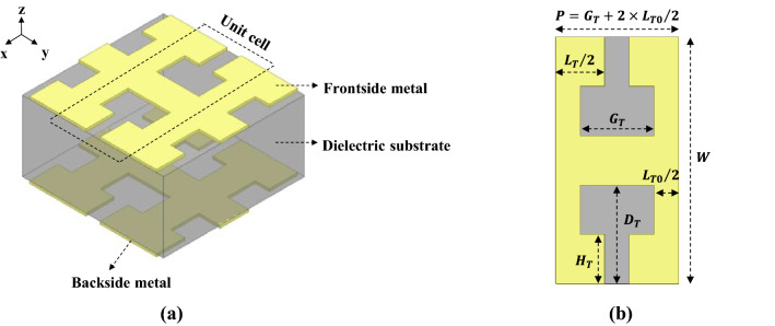
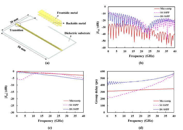
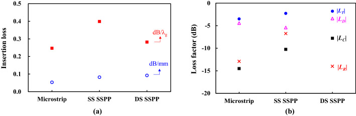
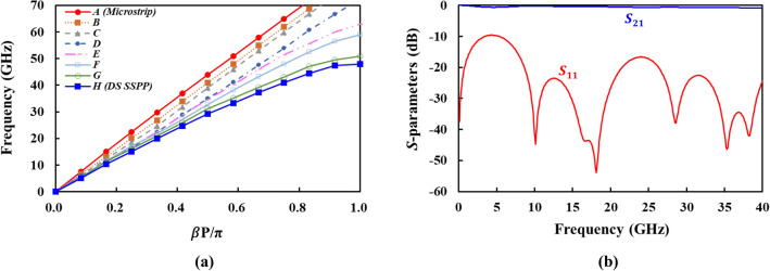
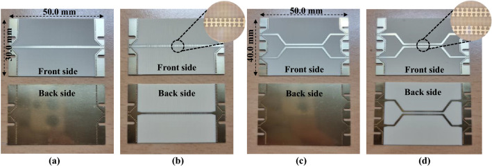
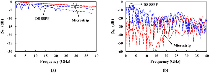
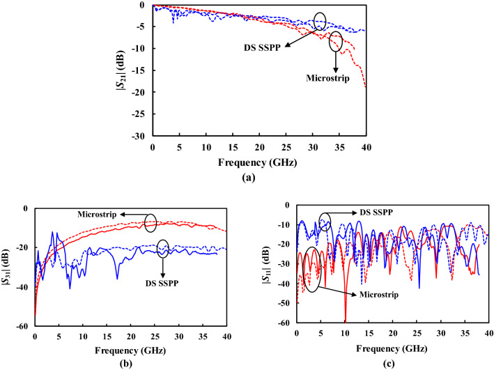
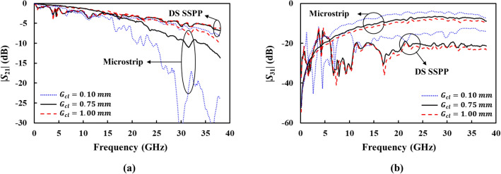
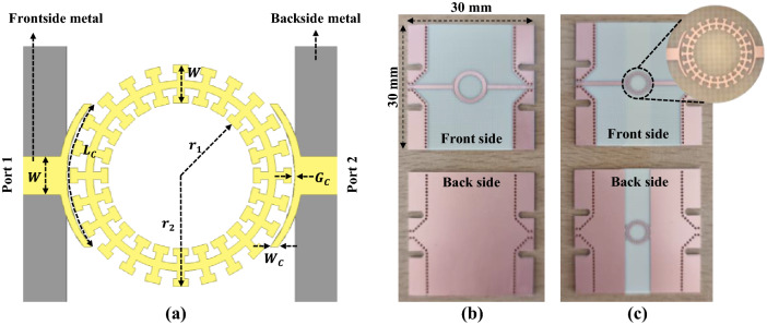
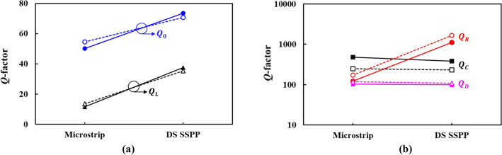
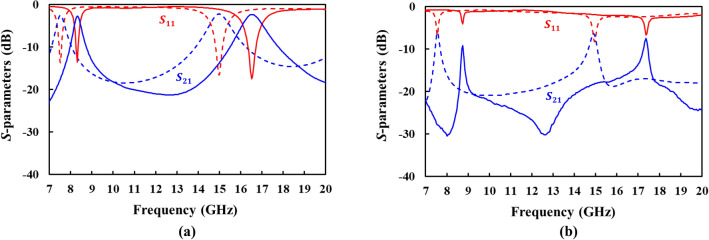
A microwave double-strip spoof surface plasmon polariton (DS SSPP) is proposed for high-speed interconnects and high-performance microwave circuits. Based on the dispersion analysis, a T-shaped double-strip structure is designed to provide strong surface- and slow-wave properties from very low to very high frequencies (~ 40 GHz). It allows the tight field confinement and greatly reduces the electromagnetic wave leakage. It exhibits broadband performance with reduced ripples in the insertion loss. It also shows more constant group delay and impedance than counterpart single-strip SSPP. The compact coaxial-to-microstrip-to-DS SSPP transition are designed using gradient grooves. The measurement shows that the DS SSPP lines can exhibit the lower coupling and lower insertion loss than the microstrip lines, so that the former is well-suited for the densely packed high-speed interconnects. The designed DS SSPP is utilized for high quality (Q)-factor microwave ring resonator. The measured unloaded Q-factor is 107.9 at the resonant frequency of 8.7 GHz, which is 1.3 times higher than the microstrip ring resonator. It is found to be caused by the reduction of the radiation loss, according to the loss analysis. The size is also reduced due to the short wavelength, occupying 56.8% of that of the microstrip ring resonator. Therefore, the proposed T-shaped DS SSPP can be also applied for high-performance miniaturized microwave circuits.
© 2022. The Author(s).
Conflict of interest statement
The authors declare no competing interests.
Figures


References
-
- Schneider MV. Microstrip lines for microwave integrated circuits. Bell Syst. Tech. J. 1969;48:1421–1444. doi: 10.1002/j.1538-7305.1969.tb04274.x. - DOI
-
- Tang WX, et al. Concept, theory, design, and applications of spoof surface plasmon polaritons at microwave frequencies. Adv. Opt. Mater. 2019;7:1800421. doi: 10.1002/adom.201800421. - DOI
-
- Zhang HC, et al. Breaking the challenge of signal integrity using time-domain spoof surface plasmon polaritons. ACS Photonics. 2015;2:1333–1340. doi: 10.1021/acsphotonics.5b00316. - DOI
-
- Zhang HC, et al. Planar spoof SPP transmission lines: Applications in microwave circuits. IEEE Microw. Mag. 2019;20:73–91. doi: 10.1109/MMM.2019.2935363. - DOI
Grants and funding
LinkOut - more resources
Full Text Sources
