. 2022 Dec:4:100018.
doi: 10.1016/j.ooc.2022.100018. Epub 2022 Jan 26.

Towards spatially-organized organs-on-chip: Photopatterning cell-laden thiol-ene and methacryloyl hydrogels in a microfluidic device

Affiliations

Towards spatially-organized organs-on-chip: Photopatterning cell-laden thiol-ene and methacryloyl hydrogels in a microfluidic device

Jennifer E Ortiz-Cárdenas et al. Organs Chip. 2022 Dec.

Abstract

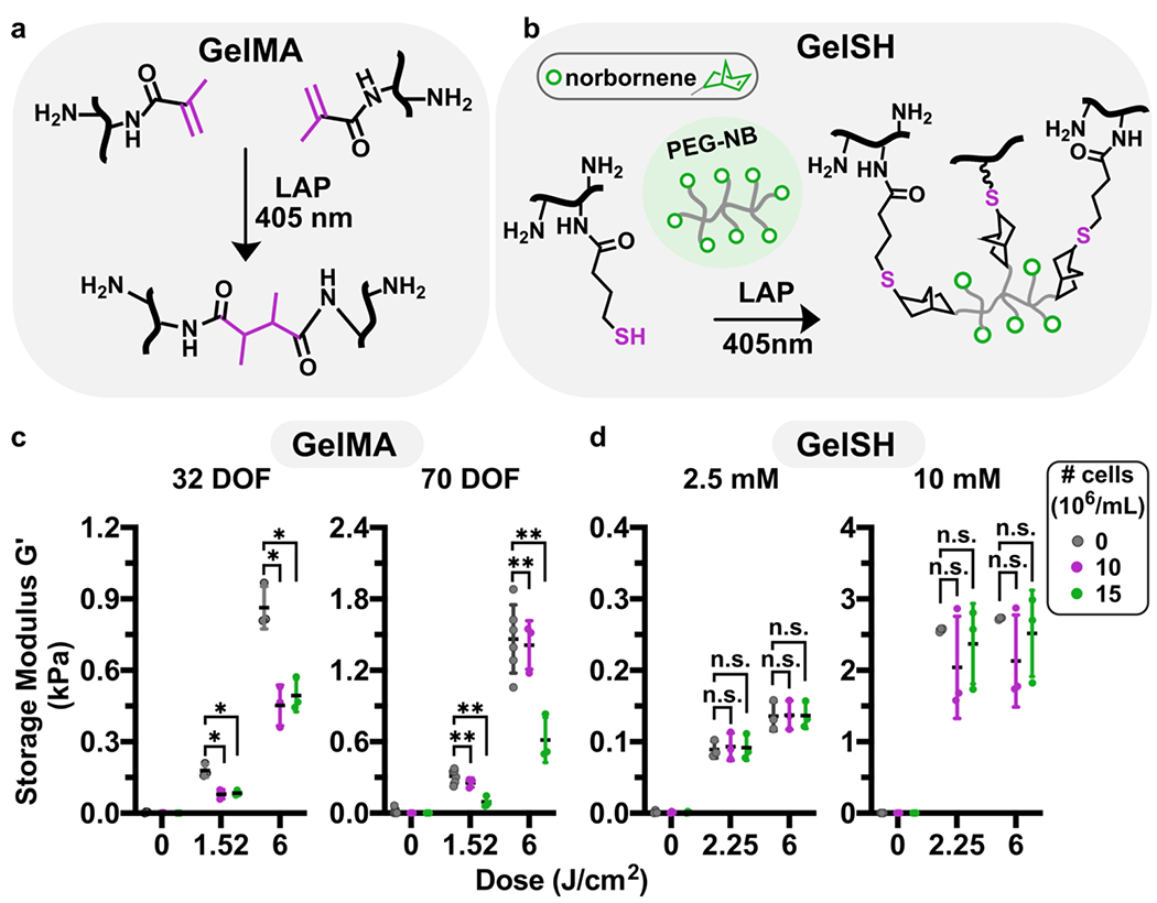
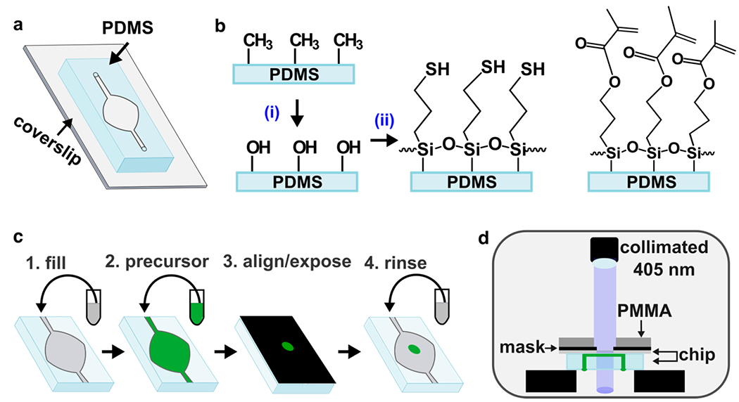
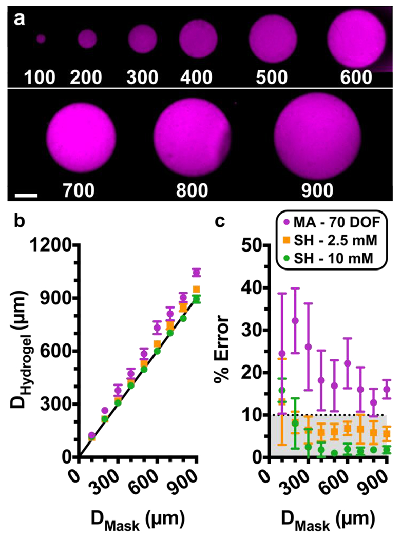
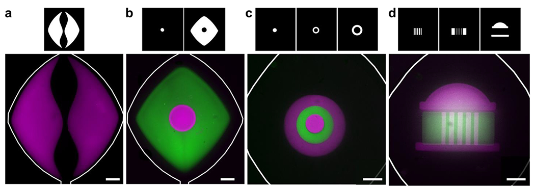
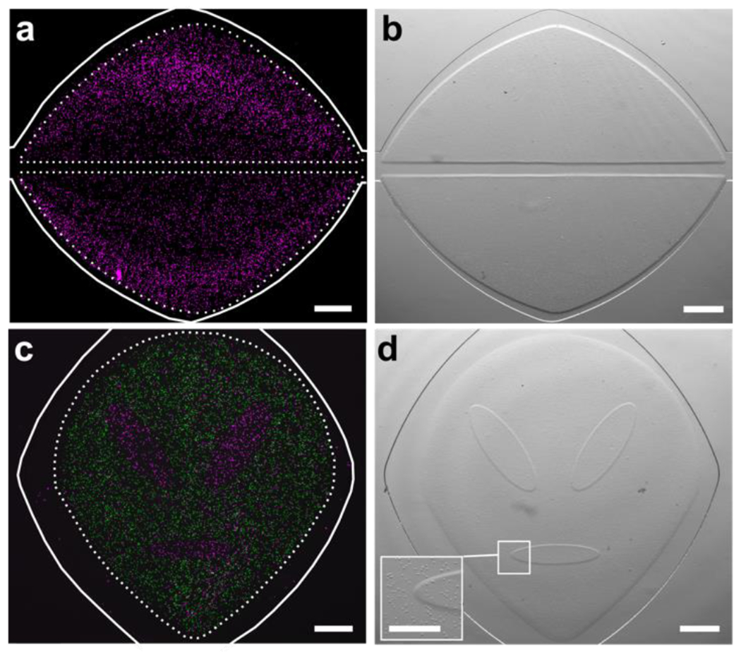
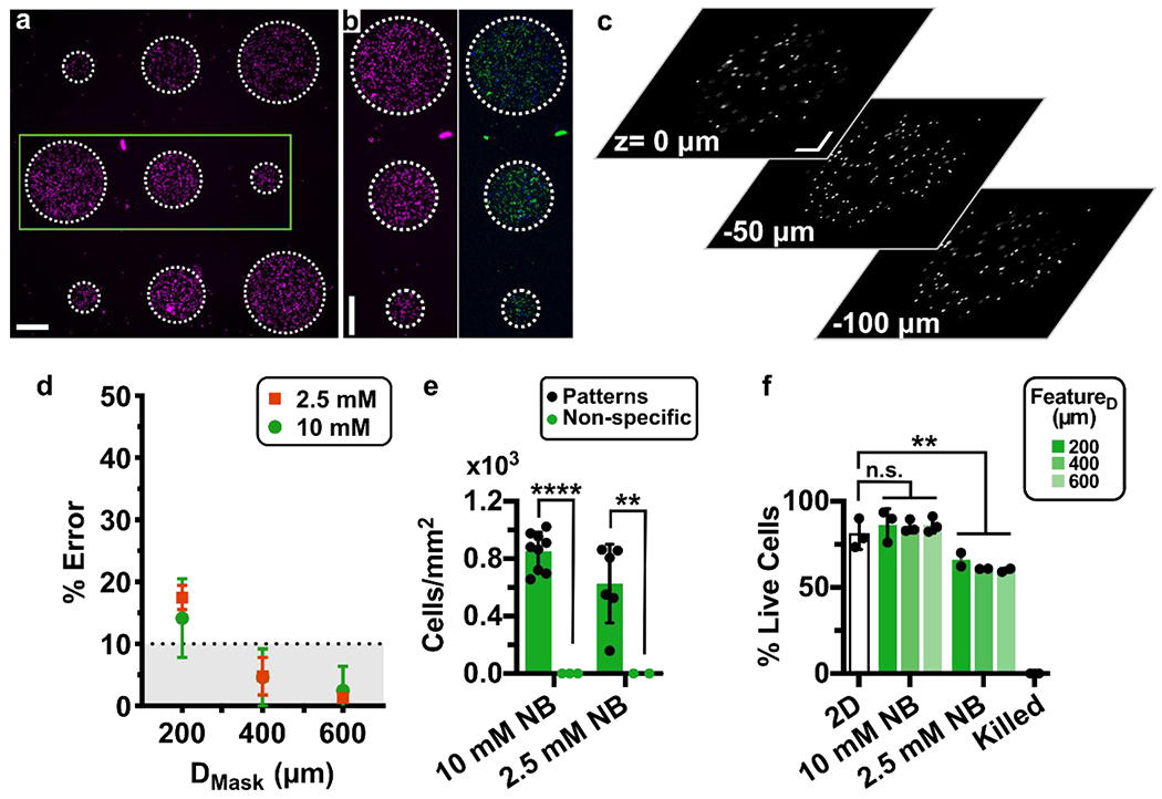
Micropatterning techniques for 3D cell cultures enable the recreation of tissue-level structures, but the combination of patterned hydrogels with organs-on-chip to generate organized 3D cultures under microfluidic perfusion remains challenging. To address this technological gap, we developed a user-friendly in-situ micropatterning protocol that integrates photolithography of crosslinkable, cell-laden hydrogels with a simple microfluidic housing, and tested the impact of crosslinking chemistry on stability and spatial resolution. Working with gelatin functionalized with photo-crosslinkable moieties, we found that inclusion of cells at high densities (≥ 107/mL) did not impede thiol-norbornene gelation, but decreased the storage moduli of methacryloyl hydrogels. Hydrogel composition and light dose were selected to match the storage moduli of soft tissues. To generate the desired pattern on-chip, the cell-laden precursor solution was flowed into a microfluidic chamber and exposed to 405 nm light through a photomask. The on-chip 3D cultures were self-standing and the designs were interchangeable by simply swapping out the photomask. Thiol-ene hydrogels yielded highly accurate feature sizes from 100 - 900 μm in diameter, whereas methacryloyl hydrogels yielded slightly enlarged features. Furthermore, only thiol-ene hydrogels were mechanically stable under perfusion overnight. Repeated patterning readily generated multi-region cultures, either separately or adjacent, including non-linear boundaries that are challenging to obtain on-chip. As a proof-of-principle, primary human T cells were patterned on-chip with high regional specificity. Viability remained high (> 85%) after 12-hr culture with constant perfusion. We envision that this technology will enable researchers to pattern 3D co-cultures to mimic organ-like structures that were previously difficult to obtain.

Keywords: GelMA; GelNB; lymphocytes; methacrylate; organs-on-chip; photopolymerization.


Conflict of interest statement

Conflict of Interest Statement The authors have no conflicts to declare.

Figures

Fig. 1
Fig. 1
Impact of cell encapsulation on storage modulus of methacryloyl and thiol-ene hydrogels. (a) Reaction scheme of GelMA (black, reactive carbons in magenta) crosslinking in presence of LAP and 405 nm light. (b) Reaction scheme of GelSH (black, thiol in magenta) with an 8-arm PEG-norbornene linker (grey, NB in green), catalyzed by the photoinitiator LAP and 405 nm light. (c,d) Shear storage moduli of GelMA and GelSH hydrogels formed in the presence or absence of cells, at varying doses of light, for (c) GelMA (10% w/v) at 32 or 70 % DOF, and (d) 5% w/v GelSH cross-linked with 2.5 or 10 mM norbornene. Legend gives density of human CD4+ T cells, in 106 cells/mL. n.s. p>0.05, * p≤0.05, ** p≤0.01 via Two-way ANOVA with Sidak’s multiple comparisons.
Fig. 2
Fig. 2
Photo-patterning set-up and process. (a) Schematic of chip: a thin layer of PDMS, patterned with a microchamber and channel by soft lithography, was bonded to a glass coverslip. (b) Surface functionalization of PDMS. The methyl surface was (i) activated via oxidation with air plasma, followed by (ii) silanization using either thiol-terminated (left) or methacrylate-terminated (right) silane, to match the intended hydrogel. (c) Stepwise schematic of patterning process: 1) The chip was filled with buffer (grey), and 2) the buffer was displaced by precursor (green). 3) A photomask with desired design was aligned against the coverslip, supported with a rigid polymer backing (PMMA), clamped (not shown for clarity), and exposed. 4) Unreacted material was removed with a buffer rinse. If needed, the process was repeated with a different precursor to add additional structures. (d) Schematic of photo-patterning set up. The chip was placed upside down on top of two support layers (black) to suspend it below the collimated light source. The channels and chamber of the chip are shown filled with precursor (green).
Fig. 3
Fig. 3
Assessing Pattern Resolution. (a) Fluorescent images of circular hydrogel features patterned on a microfluidic chip. Features ranged from 100 to 900 μm in diameter. Shown are features in GelSH with 2.5 mM NB, labelled with NHS-rhodamine, on a chip with a 0.15-mm coverslip. Scalebar 250 μm. (b-c) Quantification of accuracy. (b) Plot of measured diameter of the hydrogel region versus the diameter of the design on the photomask. Black line represents y = x, shown for reference. Measurements were taken after a 30-min incubation and rinse. (c) Calculated percent error of each feature versus the target diameter from the photomask design. The dotted line was drawn arbitrarily at 10% error, and grey area shows values that fall in that region. The shared legend shows 10% GelMA with 70% DOF (n=3) and 5% GelSH with norbornene concentrations of 2.5 mM (n=4) or 10 mM (n=4). Symbols and error bars represent mean and standard deviation; some error bars too small to see.
Fig. 4
Fig. 4
Geometric versatility achieved by on-chip photo-patterning of GelSH hydrogels. (a) NHS-rhodamine-labelled hydrogel (magenta) used to pattern a curved fluidic path in culture chamber. (b) A central circular island (magenta) surrounded by NHS-fluorescein-labelled GelSH (green). (c) Concentric circles patterned with hydrogel labelled with NHS-rhodamine and NHS-fluorescein in three sequential steps. (d) A patterned UVA Rotunda in three sequential steps. The corresponding photomasks used to achieve patterns are shown above each panel. All scalebars are 500 μm.
Fig. 5
Fig. 5
In situ photo-patterned cell-laden hydrogel constructs. (a) Fluorescence and (b) brightfield images of a patterned 3D cell culture (cells labelled magenta), patterned into two self-standing lobes. A linear fluidic path was patterned between them, and a second, curved fluidic path surrounded them for better distribution of media. (c) Fluorescence and (d) brightfield images of two distinct cell populations patterned into a lobular organ geometry. First cell population labelled with NHS-rhodamine (magenta); second population labelled with CFSE (green). Inset shows magnified boundary between two patterned regions. Scale bar is 500 μm in (a-d), 250 μm in inset. Dashed lines denote the boundary of the hydrogel regions; solid white lines indicate the edges of the microfluidic culture chamber.
Fig. 6
Fig. 6. Precision, accuracy, and viability of photo-patterned microarray of human CD4 T cells on chip after overnight culture.
(a) Nine-circle culture array patterned on-chip with cells pre-labelled with NHS-rhodamine in GelSH hydrogels. Scalebar 250 μm. (b) Zoomed-in view of area outlined in green in panel 6a. (Left) Image of NHS-rhodamine labelled cells; (Right) image after viability staining with Calcein-AM (green) and DAPI (blue). Scalebar 250 μm. (c) Images from various z planes throughout a gel feature laden with NHS-rhodamine labeled cells (representative of 600 μm features in 3 chips). Scalebar 100 μm. Z: 0 μm is near the top of the chamber, near the PDMS layer and Z: −100 μm is near the bottom of the chamber, near the glass layer. Additional images in Fig. S7. (d) Percent error of the feature diameter of cell-laden features. Patterned features were perfused overnight and compared to the intended diameter from the photomask design. (e) Quantification of cell density inside and outside of the patterned regions (n=2 and n=3 chips respectively). Two-way ANOVA with Sidak’s multiple comparisons; **** p≤0.0001, ** p≤0.01. (f) Quantification of the viability of patterned CD4+ T cells in 5% GelSH with 2.5 and 10 mM NB hydrogels as a function of feature dimensions after overnight culture (12 hr) under continuous fluid flow, versus off-chip (2D) controls (n.s. p > 0.05, ** p≤0.01 One-way ANOVA with Tukey’s multiple comparisons, n=3 and n=2 for 10 mM and 2.5 mM NB chips, respectively).

References

    1. Low LA, Tagle DA. Tissue chips – innovative tools for drug development and disease modeling. Lab Chip 2017; 17: 3026–3036. - PMC - PubMed
    1. Ronaldson-Bouchard K, Vunjak-Novakovic G. Organs-on-a-Chip: A Fast Track for Engineered Human Tissues in Drug Development. Cell Stem Cell 2018; 22: 310–324. - PMC - PubMed
    1. D’Arcangelo E, McGuigan AP. Micropatterning strategies to engineer controlled cell and tissue architecture in vitro. BioTechniques 2015; 58: 13–23. - PubMed
    1. Tenje M, Cantoni F, Porras Hernández AM, Searle SS, Johansson S, Barbe L et al. A practical guide to microfabrication and patterning of hydrogels for biomimetic cell culture scaffolds. Organs---Chip 2020; 2: 100003.
    1. Ayuso JM, Virumbrales-Muñoz M, Lacueva A, Lanuza PM, Checa-Chavarria E, Botella P et al. Development and characterization of a microfluidic model of the tumour microenvironment. Sci Rep 2016; 6. doi: 10.1038/srep36086. - DOI - PMC - PubMed