

The biomechanical fundamentals of crosslink-augmentation in posterior spinal instrumentation
- PMID: 35538122
- PMCID: PMC9090827
- DOI: 10.1038/s41598-022-11719-2
The biomechanical fundamentals of crosslink-augmentation in posterior spinal instrumentation
Abstract
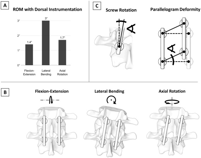
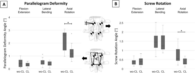
Posterior screw-rod constructs can be used to stabilize spinal segments; however, the stiffness is not absolute, and some motion can persist. While the effect of crosslink-augmentation has been evaluated in multiple studies, the fundamental explanation of their effectiveness has not been investigated. The aim of this study was to quantify the parameters "screw rotation" and "parallelogram deformation" in posterior instrumentations with and without crosslinks to analyze and explain their fundamental effect. Biomechanical testing of 15 posteriorly instrumented human spinal segments (Th10/11-L4/L5) was conducted in axial rotation, lateral bending, and flexion-extension with ± 7.5 Nm. Screw rotation and parallelogram deformation were compared for both configurations. Parallelogram deformation occurred predominantly during axial rotation (2.6°) and was reduced by 60% (-1.45°, p = 0.02) by the addition of a crosslink. Simultaneously, screw rotation (0.56°) was reduced by 48% (-0.27°, p = 0.02) in this loading condition. During lateral bending, 0.38° of parallelogram deformation and 1.44° of screw rotation was measured and no significant reduction was achieved by crosslink-augmentation (8%, -0.03°, -p = 0.3 and -13%, -0.19°, p = 0.7 respectively). During flexion-extension, parallelogram deformation was 0.4° and screw rotation was 0.39° and crosslink-augmentation had no significant effect on these values (-0.12°, -30%, p = 0.5 and -0°, -0%, p = 0.8 respectively). In axial rotation, crosslink-augmentation can reduce parallelogram deformation and with that, screw rotation. In lateral bending and flexion-extension parallelogram deformation is minimal and crosslink-augmentation has no significant effect. Since the relatively large screw rotation in lateral bending is not caused by parallelogram deformation, crosslink-augmentation is no adequate countermeasure. The fundamental understanding of the biomechanical effect of crosslink-augmentation helps better understand its potential and limitations in increasing construct stiffness.
© 2022. The Author(s).
Conflict of interest statement
All implants used for this study were kindly provided by Medacta International (Castel San Peitro, Switzerland). The providers of the implants had no role in study design, data collection and analysis, decision to publish, or preparation of the manuscript. The authors declare no competing interests.
Figures


References
MeSH terms
LinkOut - more resources
Full Text Sources
