

The accumulation of particles in ureteric stents is mediated by flow dynamics: Full-scale computational and experimental modeling of the occluded and unoccluded ureter
- PMID: 35540726
- PMCID: PMC9076127
- DOI: 10.1063/5.0083260
The accumulation of particles in ureteric stents is mediated by flow dynamics: Full-scale computational and experimental modeling of the occluded and unoccluded ureter
Abstract
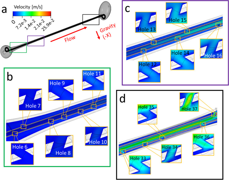
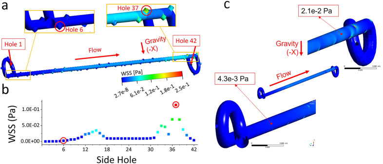
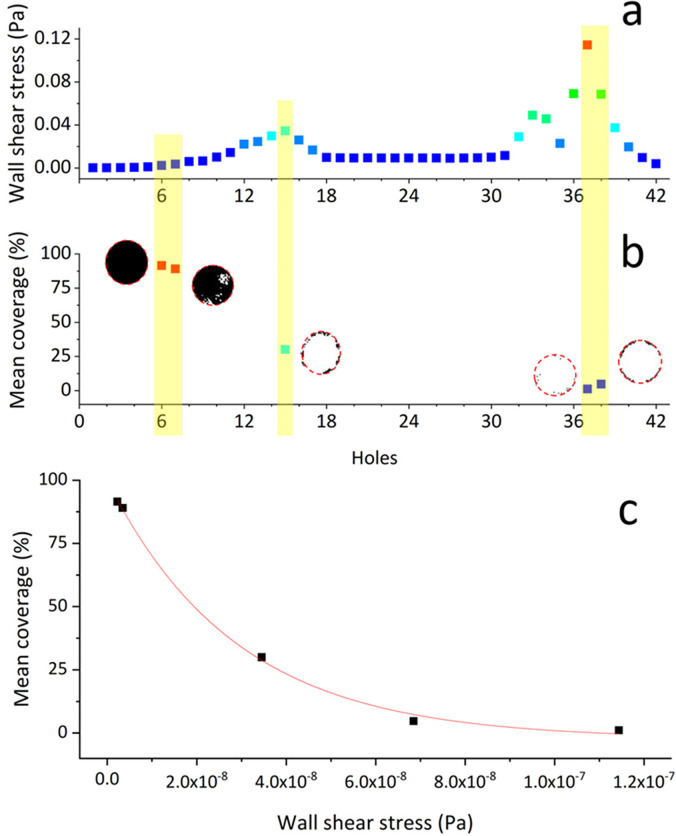
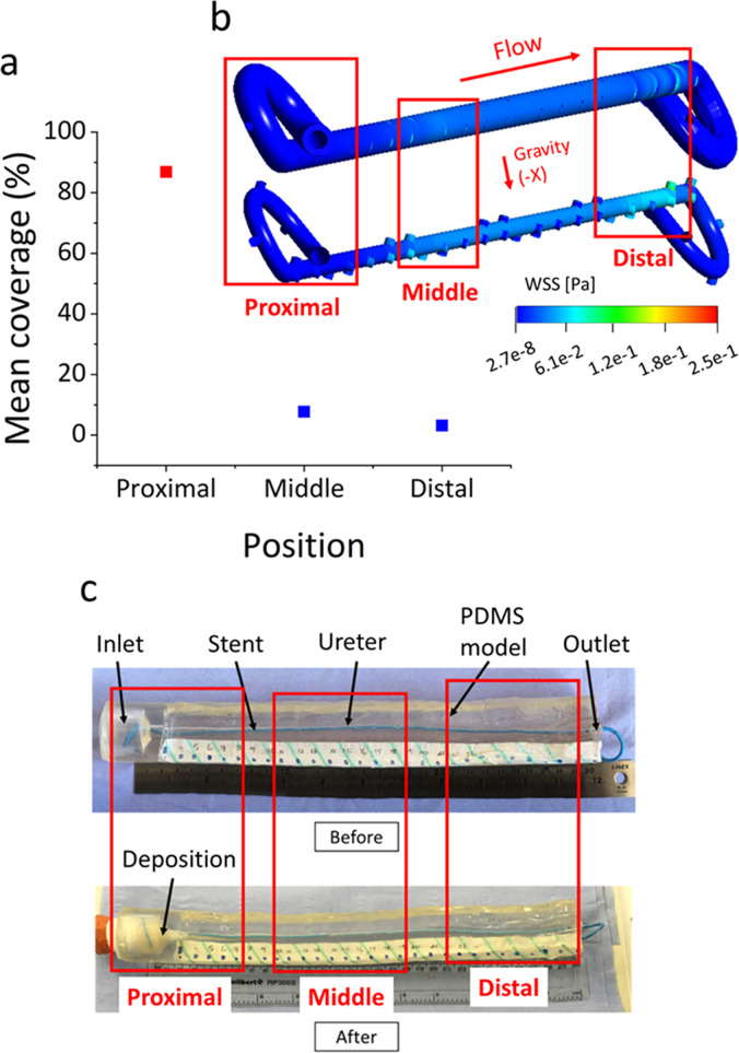
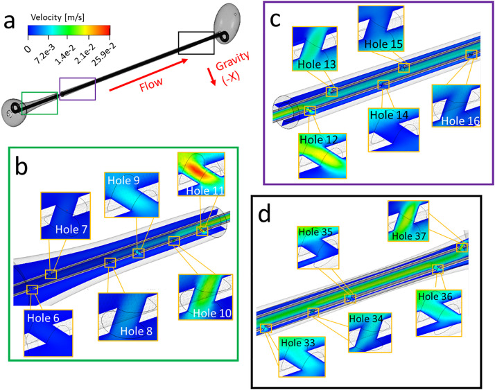
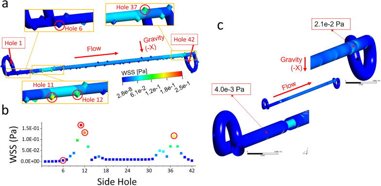
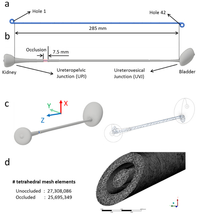
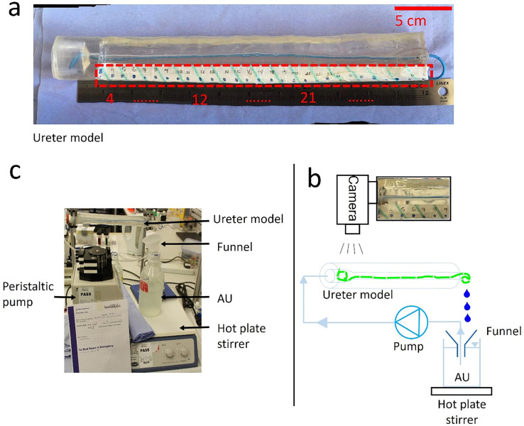
Ureteric stents are clinically deployed to restore urinary drainage in the presence of ureteric occlusions. They consist of a hollow tube with multiple side-holes that enhance urinary drainage. The stent surface is often subject to encrustation (induced by crystals-forming bacteria such as Proteus mirabilis) or particle accumulation, which may compromise stent's drainage performance. Limited research has, however, been conducted to evaluate the relationship between flow dynamics and accumulation of crystals in stents. Here, we employed a full-scale architecture of the urinary system to computationally investigate the flow performance of a ureteric stent and experimentally determine the level of particle accumulation over the stent surface. Particular attention was given to side-holes, as they play a pivotal role in enhancing urinary drainage. Results demonstrated that there exists an inverse correlation between wall shear stress (WSS) and crystal accumulation at side-holes. Specifically, side-holes with greater WSS levels were those characterized by inter-compartmental fluid exchange between the stent and ureter. These "active" side-holes were located either nearby ureteric obstructions or at regions characterized by a physiological constriction of the ureter. Results also revealed that the majority of side-holes (>60%) suffer from low WSS levels and are, thus, prone to crystals accumulation. Moreover, side-holes located toward the proximal region of the ureter presented lower WSS levels compared to more distal ones, thus suffering from greater particle accumulation. Overall, findings corroborate the role of WSS in modulating the localization and extent of particle accumulation in ureteric stents.
© 2022 Author(s).
Figures
Similar articles
-
Particle Accumulation in Ureteral Stents Is Governed by Fluid Dynamics: In Vitro Study Using a "Stent-on-Chip" Model.J Endourol. 2018 Jul;32(7):639-646. doi: 10.1089/end.2017.0946. Epub 2018 Jun 12. J Endourol. 2018. PMID: 29699424
-
Reducing deposition of encrustation in ureteric stents by changing the stent architecture: A microfluidic-based investigation.Biomicrofluidics. 2019 Jan 4;13(1):014101. doi: 10.1063/1.5059370. eCollection 2019 Jan. Biomicrofluidics. 2019. PMID: 30867872 Free PMC article.
-
A Microfluidic-Based Investigation of Bacterial Attachment in Ureteral Stents.Micromachines (Basel). 2020 Apr 13;11(4):408. doi: 10.3390/mi11040408. Micromachines (Basel). 2020. PMID: 32295085 Free PMC article.
-
Advances in Ureteral Stent Design and Materials.Curr Urol Rep. 2018 Apr 10;19(5):35. doi: 10.1007/s11934-018-0779-y. Curr Urol Rep. 2018. PMID: 29637309 Free PMC article. Review.
-
Percutaneous urinary drainage and ureteric stenting in malignant disease.Clin Oncol (R Coll Radiol). 2010 Nov;22(9):733-9. doi: 10.1016/j.clon.2010.07.004. Epub 2010 Aug 21. Clin Oncol (R Coll Radiol). 2010. PMID: 20728326 Review.
Cited by
-
Computational simulation of the flow dynamic field in a porous ureteric stent.Med Biol Eng Comput. 2022 Aug;60(8):2373-2387. doi: 10.1007/s11517-022-02620-1. Epub 2022 Jun 28. Med Biol Eng Comput. 2022. PMID: 35763188 Free PMC article.
-
Visualized bibliometric panorama of ureteral stents (1975-present): trends and hotspots revealed.World J Urol. 2025 May 30;43(1):339. doi: 10.1007/s00345-025-05723-0. World J Urol. 2025. PMID: 40445249 Review.
-
Fluid mechanical performance of ureteral stents: The role of side hole and lumen size.Bioeng Transl Med. 2022 Sep 13;8(2):e10407. doi: 10.1002/btm2.10407. eCollection 2023 Mar. Bioeng Transl Med. 2022. PMID: 36925692 Free PMC article.
-
The interplay between bacterial biofilms, encrustation, and wall shear stress in ureteral stents: a review across scales.Front Urol. 2024 Jan 16;3:1335414. doi: 10.3389/fruro.2023.1335414. eCollection 2023. Front Urol. 2024. PMID: 40778079 Free PMC article. Review.
-
Ultrasound-activated cilia for biofilm control in indwelling medical devices.Proc Natl Acad Sci U S A. 2025 May 6;122(18):e2418938122. doi: 10.1073/pnas.2418938122. Epub 2025 Apr 28. Proc Natl Acad Sci U S A. 2025. PMID: 40294275
References
-
- Drake M., Cocci A., and Pereira e Silva R., in Lower Urinary Tract Symptoms in Adults ( Springer, 2019), p. 290.
-
- Lykoudis P. S. and Roos R., J. Fluid Mech. 43, 661 (1970).10.1017/S0022112070002653 - DOI
LinkOut - more resources
Full Text Sources
Research Materials