. 2022:114:179-213.
doi: 10.1007/978-3-030-93306-7_8.

The Function and Structure of the Microsporidia Polar Tube

Affiliations

The Function and Structure of the Microsporidia Polar Tube

Bing Han et al. Exp Suppl. 2022.

Abstract

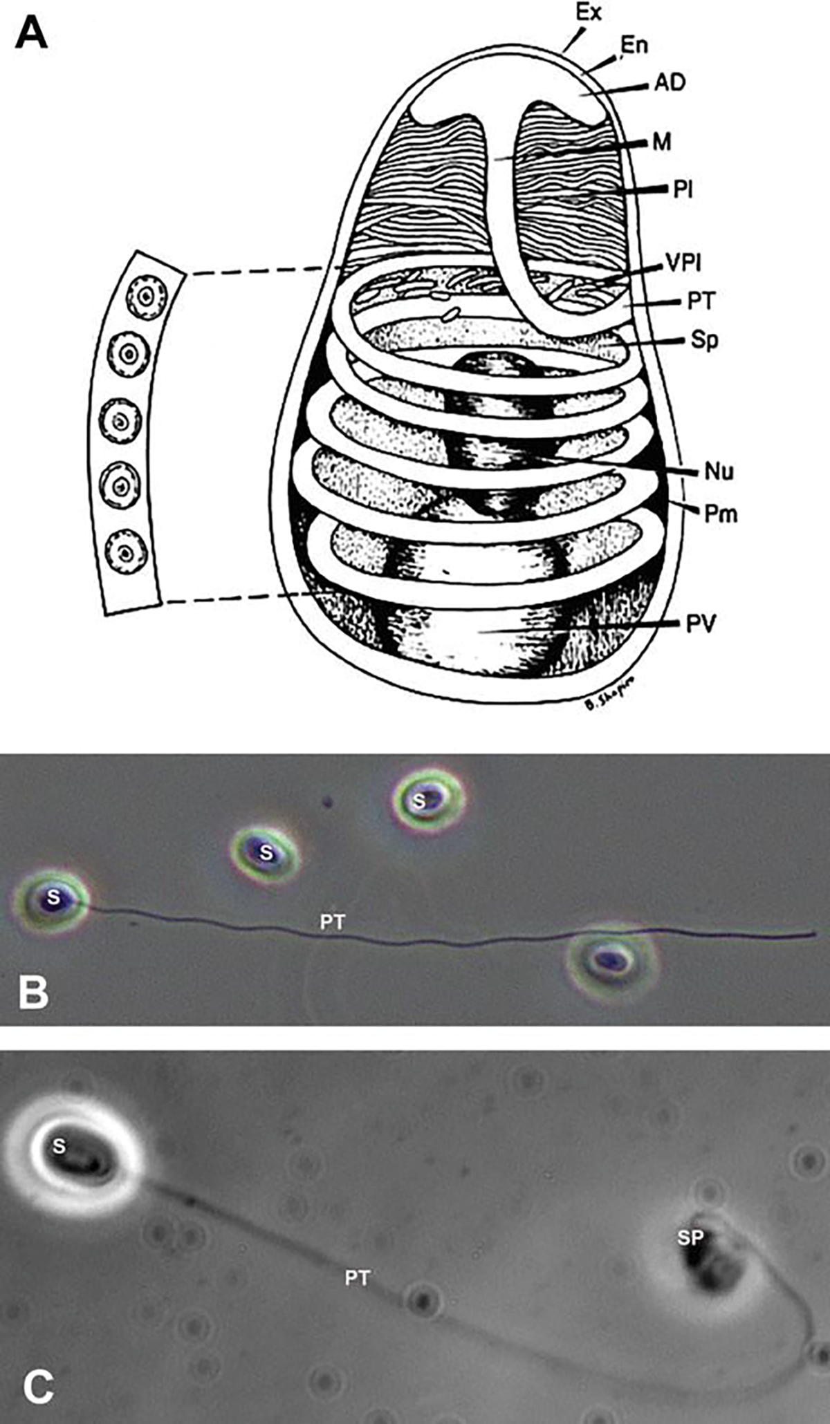
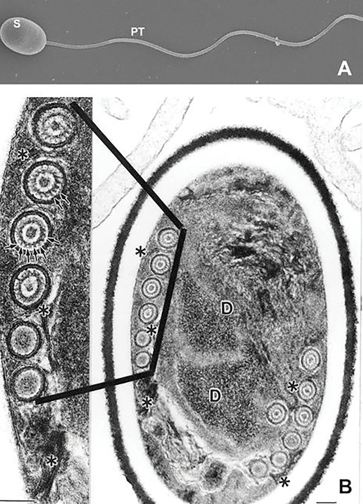
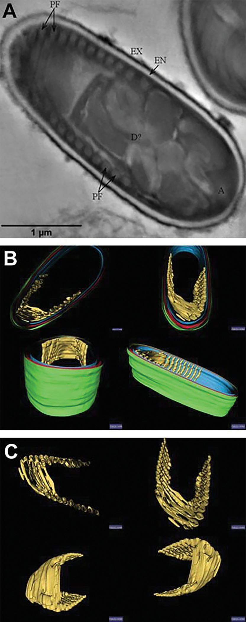
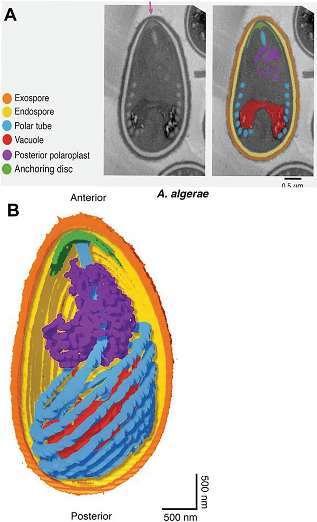
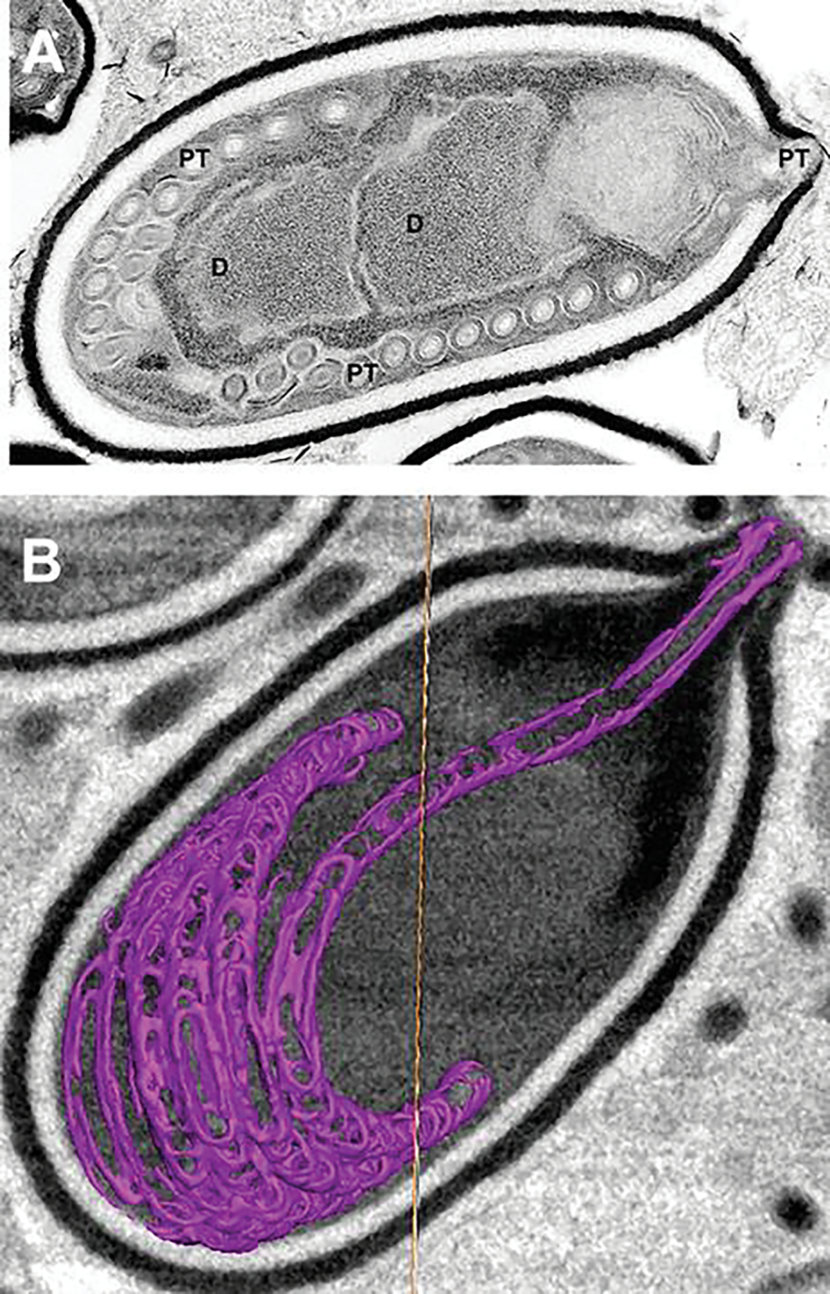
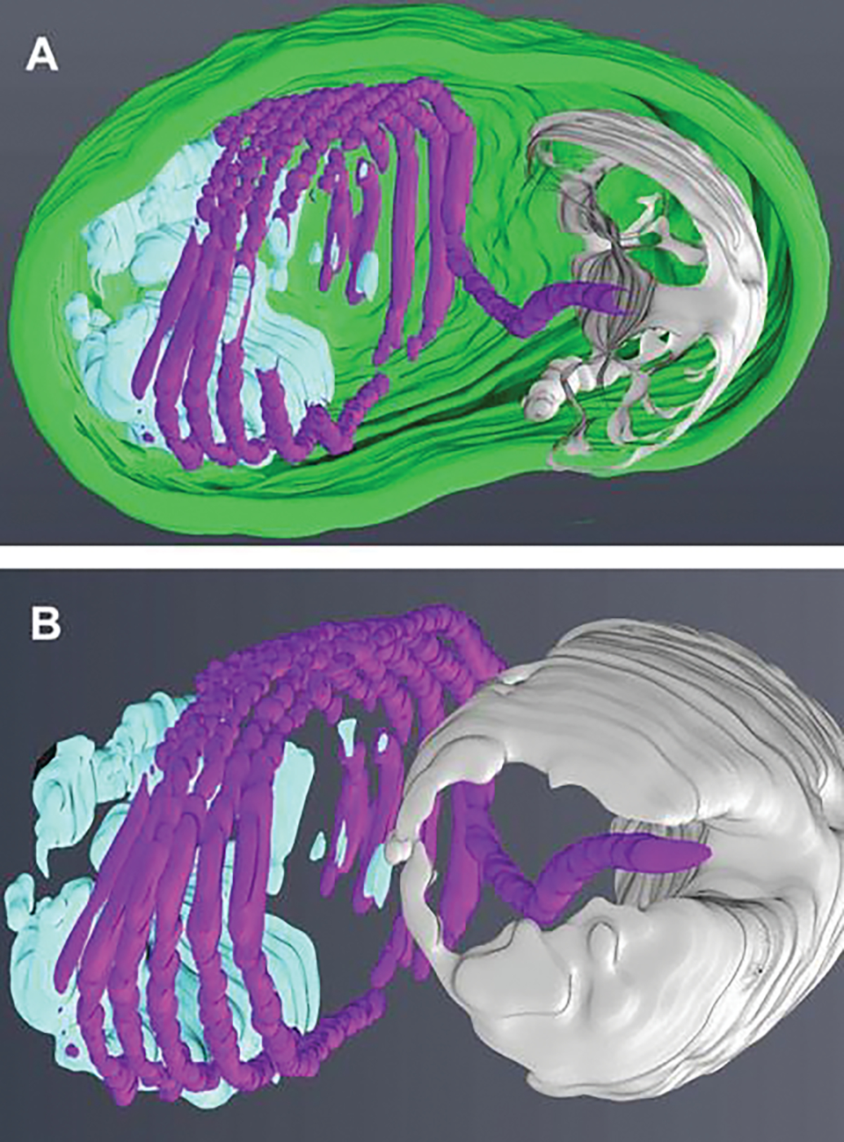
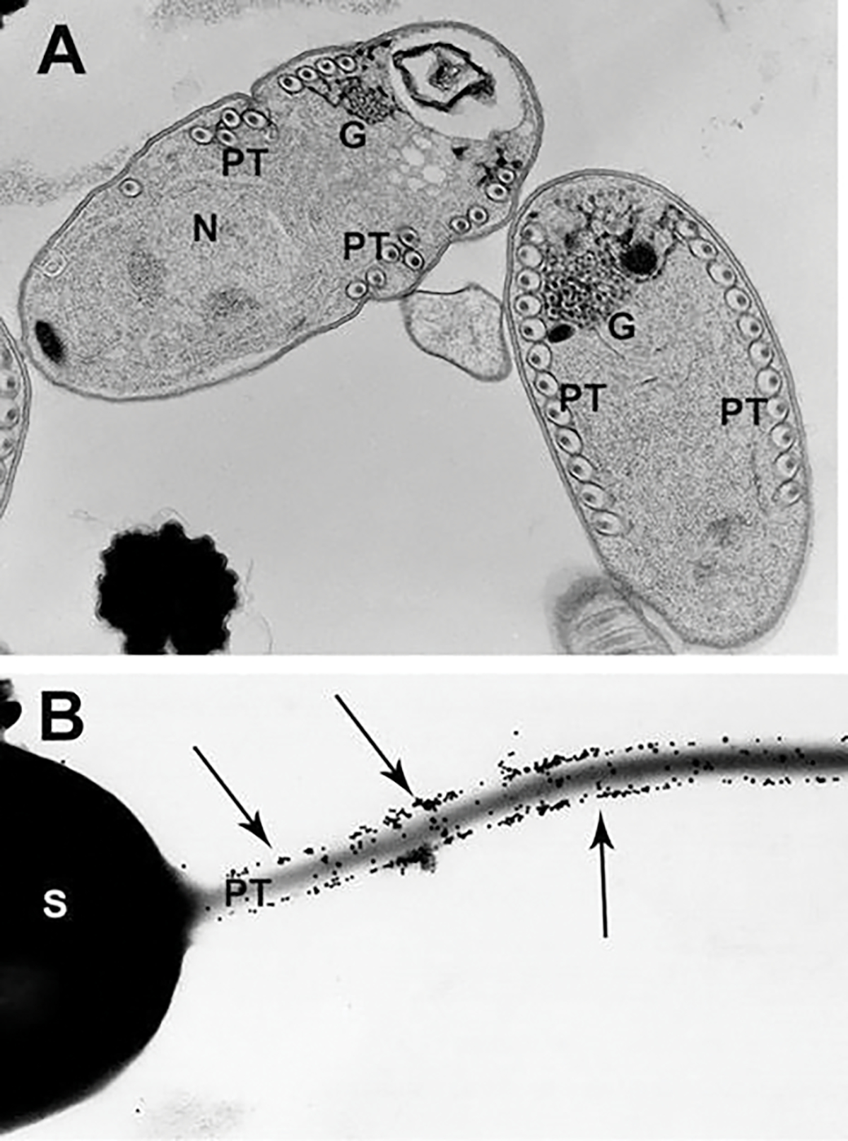
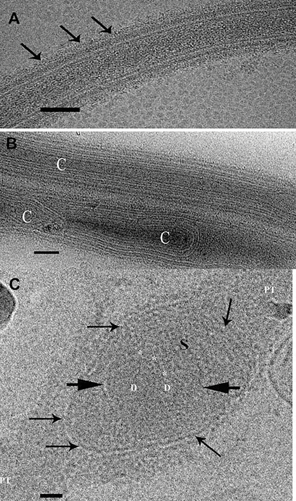
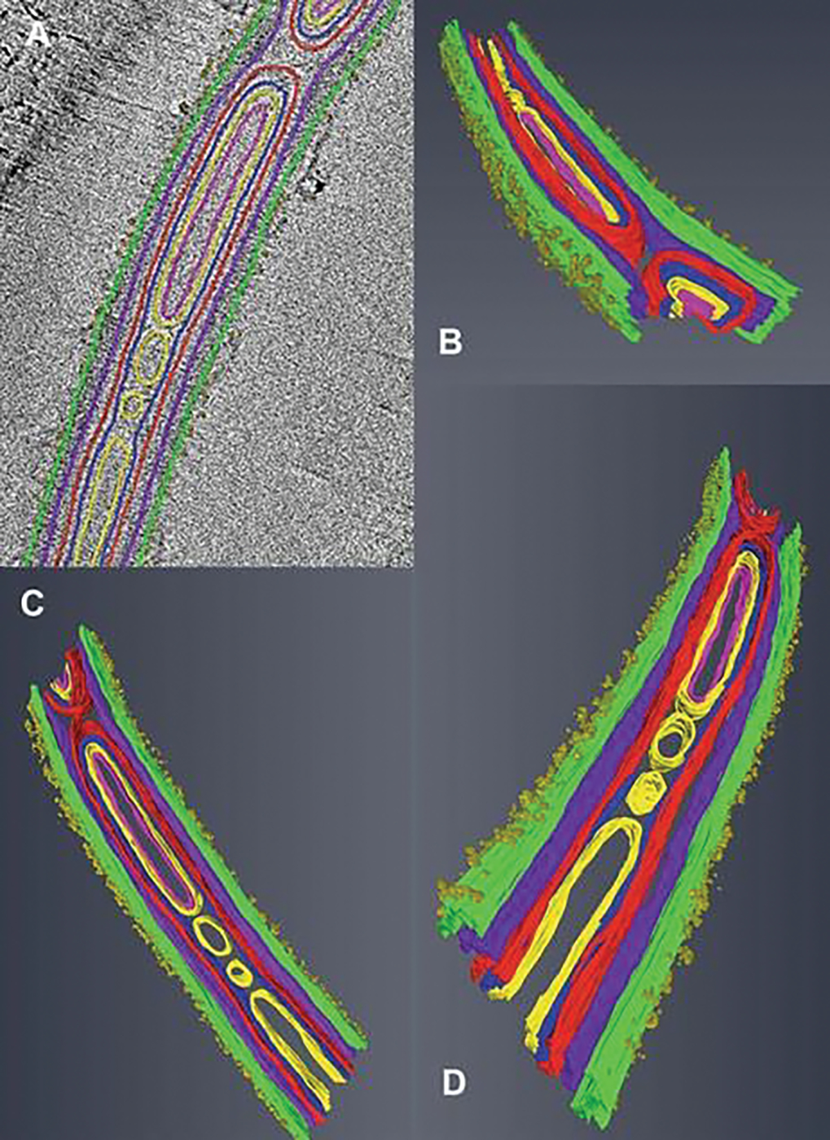
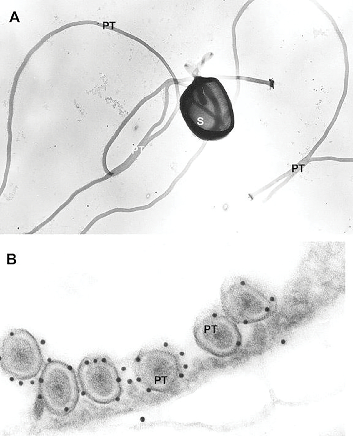
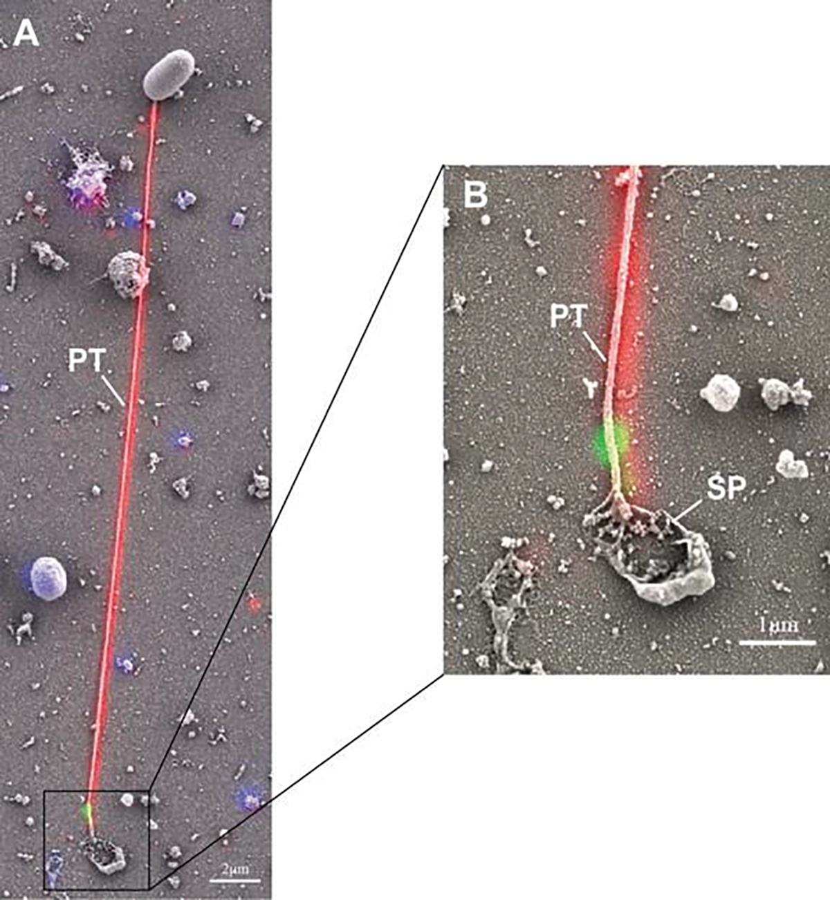
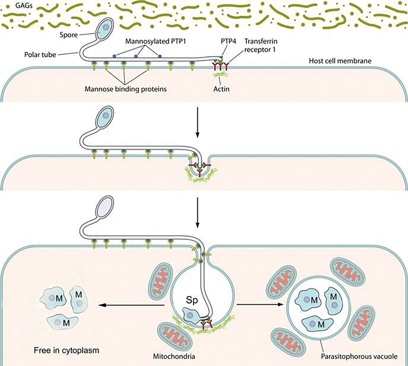
Microsporidia are obligate intracellular pathogens that were initially identified about 160 years ago. Current phylogenetic analysis suggests that they are grouped with Cryptomycota as a basal branch or sister group to the fungi. Microsporidia are found worldwide and can infect a wide range of animals from invertebrates to vertebrates, including humans. They are responsible for a variety of diseases once thought to be restricted to immunocompromised patients but also occur in immunocompetent individuals. The small oval spore containing a coiled polar filament, which is part of the extrusion and invasion apparatus that transfers the infective sporoplasm to a new host, is a defining characteristic of all microsporidia. When the spore becomes activated, the polar filament uncoils and undergoes a rapid transition into a hollow tube that will transport the sporoplasm into a new cell. The polar tube has the ability to increase its diameter from approximately 100 nm to over 600 nm to accommodate the passage of an intact sporoplasm and penetrate the plasmalemma of the new host cell. During this process, various polar tube proteins appear to be involved in polar tube attachment to host cell and can interact with host proteins. These various interactions act to promote host cell infection.

Keywords: Cell-host interaction; Diagnosis; Microsporidia; Microsporidiosis; Polar filament; Polar tube proteins; Spore; Spore wall proteins.


Conflict of interest statement

Conflict of Interest The authors declare that there is no conflict of interest.

Figures

Fig. 8.1
Fig. 8.1
Microsporidian spore structure and light microscope images. (a) Diagram of a microsporidian spore. Microsporidian spores vary in size from 1 to 12 μm. The spore coat is thinner at the anterior end of the spore and consists of an electron lucent endospore (En), electron-dense exospore (Ex), and the plasma membrane (Pm). The sporoplasm (Sp) contains ribosomes, the posterior vacuole (PV), and a single nucleus (Nu). The anchoring disc (AD) at the anterior end of the spore is the site of attachment of the polar tube. It should be noted that the polar tube is often called the polar filament when it is within the spore prior to germination. The anterior or straight region of the polar tube that connects to the anchoring disc is called the manubroid (M), and the posterior region of the tube coils around the sporoplasm. The number of coils and their arrangement (i.e., single row or multiple rows) is used in microsporidian taxonomic classification. The lamellar polaroplast (Pl) and vesicular polaroplast (VPl) surround the manubroid region of the polar tube. The insert depicts the polar tube coils in this figure in a cross section illustrating that the polar tube within the spore (i.e., polar filament) has several layers of different electron density by electron microscopy. Reprinted with permission from Keohane EM, Weiss LM. 1999. The structure, function, and composition of the microsporidian polar tube. pp. 196–224. In Wittner M, Weiss LM (ed), The Microsporidia and Microsporidiosis. ASM Press, Washington, DC (Keohane and Weiss 1999). (b) Differential interference contrast (DIC) microscopy image of Anncaliia algerae spores. One of the spores (S) has become activated, and the polar tube (PT) is in the process of extrusion. (c) Phase contrast microscopic image of an Anncaliia algerae spore (S) with the extruded polar tube (PT) and the sporoplasm (SPM) still attached to the distal end of the PT
Fig. 8.2
Fig. 8.2
Scanning and transmission electron microscopic images of microsporidian spores. (a) Scanning electron microscope image of an activated Anncaliia algerae spore (S) with the extruded polar tube (PT). (b) Transmission electron microscope (TEM) image of an Anncaliia algerae spore and an enlarged image of an area of the polar filament (PF). The spore has an electron-dense outer spore coat (exospore) overlying an inner thicker lucent region (endospore) followed by a membrane system surrounding the spore contents and polar filament coils (PF). The spore contents are composed of a complex of tightly packed arrays of membrane clusters and a centrally located sporoplasm, composed of scant cytoplasm containing a pair of abutted nuclei (diplokaryon), tightly packed ribosomes, and some endoplasmic reticulum. Surrounding this complex is a coiled polar filament (termed the polar tube (PT) when extruded) which becomes straight in the anterior part of the spore where it will exit when it is activated. The enlarged area of the PF coil cross sections illustrates the internal concentric rings and electron-dense particles (arrows) composing part of the internal structure of the PF. Images reprinted with permission from Cali A, Weiss LM, Takvorian PM (2002) Brachiola algerae spore membrane systems, their activity during extrusion, and a new structural entity, the multilayered interlaced network, associated with the polar tube and the sporoplasm. J Eukaryot Microbiol 49 (2):164–174. doi:https://doi.org/10.1111/j.1550-7408.2002.tb00361.x (Cali et al. 2002)
Fig. 8.3
Fig. 8.3
High-voltage (1.2million KV) transmission electron microscope images and three-dimensional models generated from the images of an Anncaliia algerae spore. (a) High-voltage transmission electron microscope (HVTEM) image of a 400-nm-thick section obtained with a 1.2 million accelerating voltage. One hundred and twenty one (121) images of the section were taken at 0–600 tilt angles at two degree increments from the four aspects for a total of 120 tilt images plus the original zero tilt position. The images were then aligned, “Z” stack, and a volume of the images was produced. Slice number 52 of the volume is of a nonactivated Anncaliia algerae spore. The exospore (EX), endospore (EN), diplokaryion (D), anchoring disk (A), and polar filament (PF) are all visible. (b) HVTEM three-dimensional model of the spore generated from the 121 tilt series image volume segmented with Amira© software. The exospore (EX) is green, endospore (EN) is red, the spore wall inner membranes are blue, and the polar filament is gold in this rendering. The spore models are tilted to enable different viewing angles of the PF inside the spore. (c) HVTEM three-dimensional model of the segmented polar filament obtained from the volume in Fig. 8.3a. The model illustrates the uniform orientation of the PF. The models are tilted to enable different viewing angles of the PF. These various images were obtained by Dr. Peter M. Takvorian using equipment at the Resource for Visualization of Biological Complexity, NYS Department of Health Wadsworth Center, Empire State Plaza, P.O. Box 509, Albany, NY 12201, USA
Fig. 8.4
Fig. 8.4
Serial block-face scanning electron microscopy (SBFSEM) imaging of intact Anncaliia algerae spores. (a) Serial block-face scanning electron microscopy imaging of intact Anncaliia algerae spores. Samples were serially sliced at 50 nm thickness (left), and images for a representative slice are shown. (b) Representative SBFSEM slice highlighting segmented organelles. Original micrograph is shown (left), as well as the same image with color overlays indicating segmented organelles (right): exospore (orange), endospore (yellow), PT (blue), vacuole (red), posterior polaroplast (purple), and anchoring disc (green). Magenta arrow indicates the thinnest part of the endospore layer where the anchoring disc is localized. (c) Representative 3D reconstruction of an Anncaliia algerae spore from SBFSEM data. Each color represents an individual organelle, color code as in (b). Images reprinted with permission from Jaroenlak P, Cammer M, Davydov A, Sall J, Usmani M, Liang F-X, Ekiert D, Kroon G (2020a) 3-Dimensional organization and dynamics of the microsporidian polar tube invasion machinery. PLoS pathogens 16:e1008738. doi:https://doi.org/10.1371/journal.ppat.1008738 (Jaroenlak et al. 2020)
Fig. 8.5
Fig. 8.5
Transmission electron microscope (TEM) image and focused ion beam scanning electron microscope image of an activated Anncaliia algerae spore. (a) TEM image of an activated Anncaliia algerae spore starting the extrusion process. The internal organization of the spore undergoes massive membrane reorganization while the polar filament changes, becoming a hollow tube as it everts and starts exiting the spore through the anterior anchoring disk (A) and the opening of the spore wall. The PF has translocated, and the diplokaryon (D) is in the middle the spore and in a tandem relationship. (b) Focused ion beam scanning electron microscope (FIB-SEM) image from a tomogram generated from 15-nm-thick “Z” stack images of an activated Anncaliia algerae spore with an extruding polar filament. The polar filament was segmented with Amira© software to produce a 3-D rendering. The spore image has an overlay of the uncoiling polar filament (purple) exiting the anterior thin exospore wall. The spore wall has erupted forming a collar through which the PT is exiting. The collar is composed of part of the anchoring disc, polaroplast, and exospore wall. These various images were obtained by Dr. Peter M. Takvorian with assistance from Dr. William J. Rice and Ashleigh Raczkowski using equipment at the Simons Electron Microscopy Center New York Structural Biology Center 89 Convent Avenue, NY, NY 10027
Fig. 8.6
Fig. 8.6
Three-dimensional models generated from “Z” stack images obtained from focused ion beam scanning electron microscopy (FIB-SEM). (a) A three-dimensional model generated from the 15-nm-thick “Z” stack image volume (see Fig. 8.5b) obtained with an FIB-SEM. The image stacks of the activated spore are aligned and then segmented with Amira© software. The segmented areas are the exospore (green), the anchoring disc-polaroplast complex (silver), the polar tube (purple), and the posterior vacuole and membranes (light blue). (b) A three-dimensional model of the segmented spore (see Fig. 8.5b) containing internal organelles, anchoring disc-polaroplast complex (silver), the polar tube (purple), and the posterior vacuole and membranes (light blue). The removal of the exospore wall and rotation of the model to show the anterior aspect of the PT and anchoring disc complex provides a view of the exiting PT passing through the complex as it uncoils and straightens. These various images were obtained by Dr. Peter M. Takvorian with assistance from Dr. William J. Rice and Ashleigh Raczkowski using equipment at the Simons Electron Microscopy Center New York Structural Biology Center 89 Convent Avenue, NY, NY 10027
Fig. 8.7
Fig. 8.7
Transmission electron microscope (TEM) image of polar filament formation and post-transcriptional glycosylation of the filament involving the Golgi. (a) TEM image of Glugea stephani sporoblasts containing developing polar filaments (PF), enzyme histochemically labeled for Golgi. The electron-dense reaction product (RP) outlines each outer layer of the filament, and fenestrated clusters of RP are present on the Golgi complex-filament interface. During PF development, the polar tube proteins are posttranslationally modified by the Golgi. (b) TEM image of an Anncaliia algerae spore with extruding polar tube. The spore was immune-gold labeled to demonstrate the presence of Con A on the polar tube. Note the large numbers of 12-nm gold particle labeling the polar tube surface. Reprinted with permission from Xu Y, Takvorian PM, Cali A, Orr G, Weiss LM (2004) Glycosylation of the major polar tube protein of Encephalitozoon hellem, a microsporidian parasite that infects humans. Infection and immunity 72 (11):6341–6350. doi: https://doi.org/10.1128/IAI.72.11.6341-6350.2004 (Xu et al. 2004)
Fig. 8.8
Fig. 8.8
Transmission electron microscope images of Anncaliia algerae extruded polar tubes that are cryogenically preserved and imaged while frozen. (a) Cryo-TEM image of a cryogenically preserved extruded polar tube (PT). Multiple layers of varying densities are visible. The outermost surface edge is covered with the fine fibrils (arrows). Bar is 50 nm. (b) Cryo-TEM image of two polar tube (PT) segments that contain various forms of material. The upper tube has multiple layers of membrane-like material arranged parallel to the orientation of the tube and surrounding a narrow long cylinder (C). The lower PT contains membrane-like and tubular structures, some of which bend around cylinders (C). Bar is 50 nm. (c) Cryo-TEM image of a polar tube (PT) that contains a membrane enclosed (arrows) sporoplasm (S) inside the tube. The oval- or sperm head-shaped sporoplasm has greatly distended a portion of the tube. The sporoplasm contains medium-dense material, and a membrane (short arrows) encloses two nuclei in a diplokaryon (D) arrangement. The membrane enclosed nuclear region has an indentation, and three or four small circular structures are abutted to it (*). Bar is 50 nm. Images reprinted with permission from Takvorian PM, Han B, Cali A, Rice WJ, Gunther L, Macaluso F, Weiss LM (2020) An Ultrastructural Study of the Extruded Polar Tube of Anncaliia algerae (Microsporidia). J Eukaryot Microbiol 67 (1): 28–44. doi:https://doi.org/10.1111/jeu.12751 (Takvorian et al. 2020)
Fig. 8.9
Fig. 8.9
Tomograms and three-dimensional models generated from cryo-TEM “Z” stacks of aligned images. (a–d) Tomogram of a portion of polar tube (PT) containing membranes, cylinders, and its surface is covered with tufts of fibrillar material. The tomogram was segmented and 3D models were generated from it using Amira© software. The colors are assigned to different structures inside and on the surface of the polar tube. The fibril tufts are visible on the surface of the PT. The models are tilted at various angles to enable observation of different internal structures and their relationships. Images reprinted with permission from Takvorian PM, Han B, Cali A, Rice WJ, Gunther L, Macaluso F, Weiss LM (2020) An Ultrastructural Study of the Extruded Polar Tube of Anncaliia algerae (Microsporidia). J Eukaryot Microbiol 67 (1):28–44. doi:https://doi.org/10.1111/jeu.12751 (Takvorian et al. 2020)
Fig. 8.10
Fig. 8.10
Transmission electron microscope images of a mechanically disrupted spore and polar tubes used during production of polar tube protein antibodies. (a) TEM image of Glugea americanus (Spraguea americana) spores mechanically disrupted with glass beads, washed in 1% SDS and 9 M urea, and negatively stained with uranyl acetate. The spore is broken open, part of the PT is still inside it, and several intact PTs are present. (b) TEM image of Glugea americanus (Spraguea americana) polar filament immunogold labeled for polar tube protein 1 (PTP-1). A cross section of six PF coils is visible and 12-nm gold secondary labels the primary antibody raised against PTP-1. Most of the gold is attached to the outer PT layer. Images reprinted with permission from Keohane EM, Orr GA, Takvorian PM, Cali A, Tanowitz HB, Wittner M, Weiss LM (1996) Identification of a microsporidian polar tube reactive antibody. J. Euk Microbiol. 43(1): 26–31. (Keohane et al. 1996)
Fig. 8.11
Fig. 8.11
Correlative light and electron microscopy (CLEM) analysis of germination of Encephalitozoon hellem. Encephalitozoon hellem-infected tissue cultures were incubated with rabbit polyclonal to EhPTP1 (red) and murine monoclonal to EhPTP4 (green). The fluorescence image and SEM image of the same site were taken sequentially, and the fluorescence images with labeling of EhPTP4 and the polar tube were correlated to the SEM images which demonstrated the germination of a microsporidium at high resolution. Panel (a) shows an extruded polar tube with EhPTP4 staining at the end of the polar tube (PT). Panel (b) shows the enlarged section of panel (A), and the droplet of released sporoplasm (SP) was still attaching to the tip of polar tube. Reprinted with the permission from Han B, Polonais V, Sugi T, Yakubu R, Takvorian PM, Cali A, Maier K, Long M, Levy M, Tanowitz HB (2017a) The role of microsporidian polar tube protein 4 (PTP4) in host cell infection. PLoS pathogens 13 (4):e1006341 (Han et al. 2017)
Fig. 8.12
Fig. 8.12
A model of polar tube adherence and invasion. This model is based primarily on data collected using Encephalitozoon spp. as a model for host cell invasion. The spore wall contains spore wall proteins (e.g., EnP1, NbSWP7, NbSWP9, NbSWP11, NbSWP12, and NbSWP16) that can interact and adhere to glycosaminoglycans (GAGs) and other substances in the mucin layer (green) of the gastrointestinal track or can interact with GAGs on the surface of host cells. These interactions are probably involved in germination. As the polar tube germinates, the polar tube adheres to the host surface by interactions of polar tube protein 1 (PTP1) with host cell surface mannose-binding proteins (MBP). This allows the polar tube to form an invasion synapse by pushing into the host cell membrane. In the formation of the invasion synapse, interactions of PTP1 (and possibly PTP4) with the host cell membrane result in the establishment of a protected microenvironment for the extruded microsporidian sporoplasm which excludes the external environment. Within the invasion synapse, epitopes of polar tube protein 4 (PTP4) that are exposed at the tip of polar tube interact with transferrin receptor 1 (TfR1), and possibly other host cell interacting proteins (HCIPs), at the host cell plasma membrane triggering signaling events. During the final steps of invasion, these various interactions lead to the formation of the invasion vacuole which can include clathrin-mediated endocytosis as well as the involvement of host cell actin. The sporoplasm (and meront) possess surface proteins, such as sporoplasm protein 1 (SSP1), which interact with various host cell surface proteins tethering the sporoplasm to the plasma membrane during invasion facilitating development of the invasion vacuole. At this early stage of infection, host mitochondria are already located around the invasion vacuole. For microsporidia that develop in the cytoplasm (arrow on the left), such as Nosema spp. and Anncaliia spp., the organisms penetrate the invasion vacuole, and meronts can be seen undergoing development within the cytoplasm of the host cell. For microsporidia that develop in a parasitophorous vacuole (arrow on right), such as Encephalitozoon spp., the invasion vacuole completes its internalization of the sporoplasm; it becomes a meront and starts replicating. The meront surface interacts with the invasion vacuole membrane forming electron-dense membrane structures that allows meront SSP1 to interact with voltage-dependent anion selective channels (VDAC) located on the outer membrane of the mitochondria. The interaction of SSP1 and VDAC appears to play a crucial role in association of host cell mitochondria with the invasion vacuole facilitating energy acquisition from the host cell by replicating meronts. Adapted with permission from Han B, Pan G, Weiss LM (2021) Microsporidiosis in Humans. Clin Microbiol Rev.:e0001020. doi:https://doi.org/10.1128/CMR.00010-20 (Han et al. 2021)

Similar articles

Cited by

References

    1. Aurrecoechea C, Barreto A, Brestelli J, Brunk BP, Caler EV, Fischer S, Gajria B, Gao X, Gingle A, Grant G, Harb OS, Heiges M, Iodice J, Kissinger JC, Kraemer ET, Li W, Nayak V, Pennington C, Pinney DF, Pitts B, Roos DS, Srinivasamoorthy G, Stoeckert CJ Jr, Treatman C, Wang H (2011) AmoebaDB and MicrosporidiaDB: functional genomic resources for Amoebozoa and microsporidia species. Nucleic Acids Res 39(Database Issue):D612–D619. 10.1093/nar/gkq1006 - DOI - PMC - PubMed
    1. Beznoussenko GV, Dolgikh VV, Seliverstova EV, Semenov PB, Tokarev YS, Trucco A, Micaroni M, Di Giandomenico D, Auinger P, Senderskiy IV, Skarlato SO, Snigirevskaya ES, Komissarchik YY, Pavelka M, De Matteis MA, Luini A, Sokolova YY, Mironov AA (2007) Analogs of the Golgi complex in microsporidia: structure and avesicular mechanisms of function. J Cell Sci 120(Pt 7):1288–1298. 10.1242/jcs.03402 - DOI - PubMed
    1. Bohne W, Ferguson DJ, Kohler K, Gross U (2000) Developmental expression of a tandemly repeated, glycine-and serine-rich spore wall protein in the microsporidian pathogen Encephalitozoon cuniculi. Infect Immun 68(4):2268–2275 - PMC - PubMed
    1. Bouzahzah B, Weiss LM (2010) Glycosylation of the major polar tube protein of Encephalitozoon cuniculi. Parasitol Res 107(3):761–764. 10.1007/s00436-010-1950-7 - DOI - PMC - PubMed
    1. Bouzahzah B, Nagajyothi F, Ghosh K, Takvorian PM, Cali A, Tanowitz HB, Weiss LM (2010) Interactions of Encephalitozoon cuniculi polar tube proteins. Infect Immun 78(6):2745–2753. 10.1128/IAI.01205-09 - DOI - PMC - PubMed

LinkOut - more resources