. 2022 May 13;8(19):eabm9132.
doi: 10.1126/sciadv.abm9132. Epub 2022 May 11.

Real-time 3D optoacoustic tracking of cell-sized magnetic microrobots circulating in the mouse brain vasculature

Affiliations

Real-time 3D optoacoustic tracking of cell-sized magnetic microrobots circulating in the mouse brain vasculature

Paul Wrede et al. Sci Adv. .

Abstract

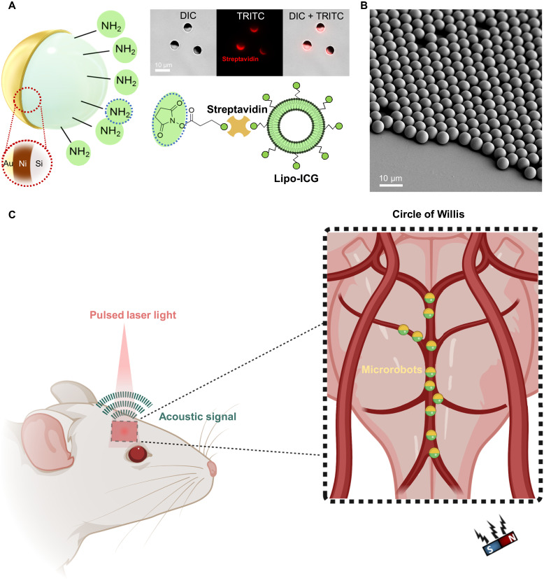
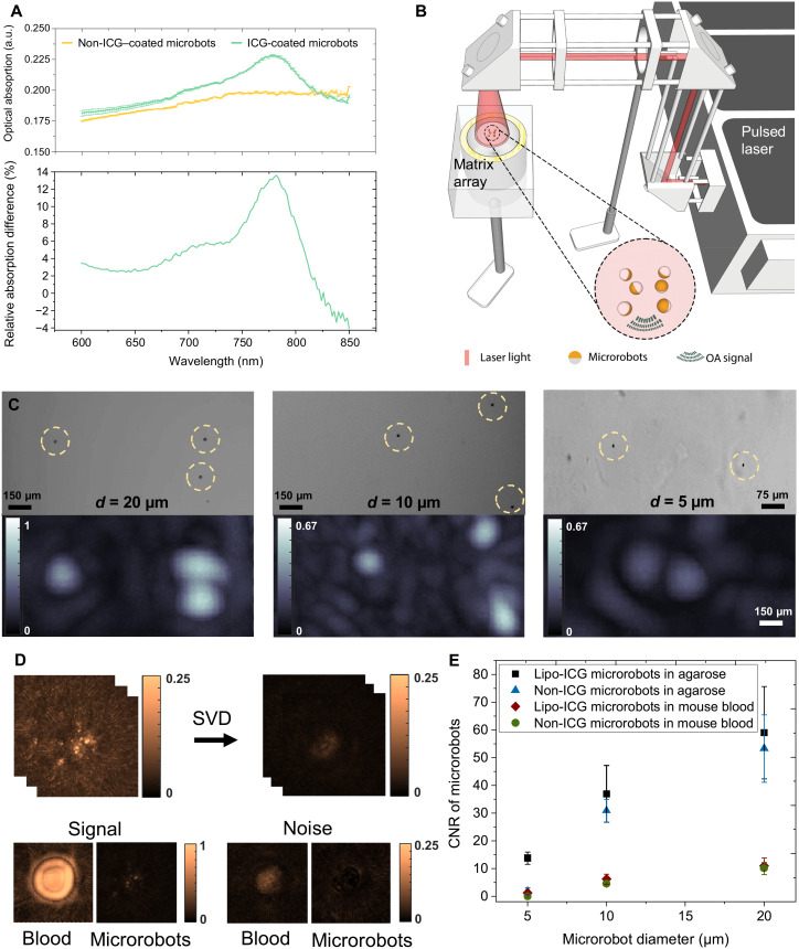
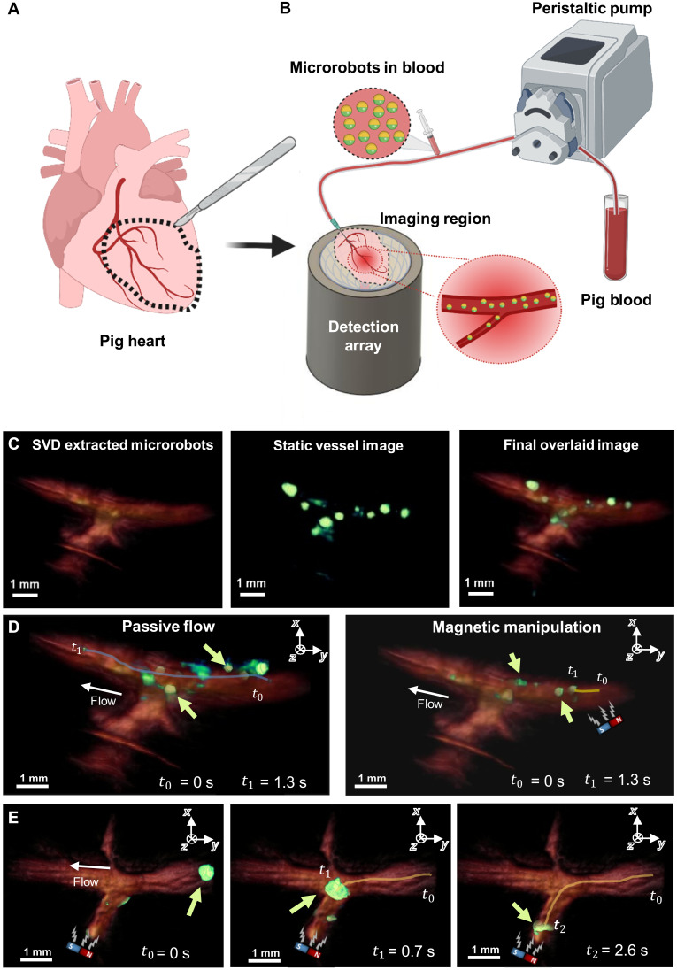
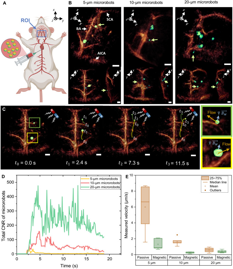
Mobile microrobots hold remarkable potential to revolutionize health care by enabling unprecedented active medical interventions and theranostics, such as active cargo delivery and microsurgical manipulations in hard-to-reach body sites. High-resolution imaging and control of cell-sized microrobots in the in vivo vascular system remains an unsolved challenge toward their clinical use. To overcome this limitation, we propose noninvasive real-time detection and tracking of circulating microrobots using optoacoustic imaging. We devised cell-sized nickel-based spherical Janus magnetic microrobots whose near-infrared optoacoustic signature is enhanced via gold conjugation. The 5-, 10-, and 20-μm-diameter microrobots are detected volumetrically both in bloodless ex vivo tissues and under real-life conditions with a strongly light-absorbing blood background. We further demonstrate real-time three-dimensional tracking and magnetic manipulation of the microrobots circulating in murine cerebral vasculature, thus paving the way toward effective and safe operation of cell-sized microrobots in challenging and clinically relevant intravascular environments.


Figures

Fig. 1.
Fig. 1.. Microrobot design and experimental procedure of optoacoustic tracking and magnetic manipulation.
(A) Schematics depicting the coating composition of the microcapillary-sized magnetic microrobots used in this study. The microrobots were coated with 120-nm layer of Ni, 50-nm layer of Au, and liposomal ICG (Lipo-ICG). The Ni coating allowed for magnetic manipulation of the microrobots. Both the Au and Liposome ICG coatings were used for enhancing the OAT contrast. (Top right) A bright-field differential interference contrast (DIC) microscope image of the 5-μm-diameter Janus microrobots. The streptavidin coating necessary to bind Lipo-ICG to the microrobots is indicated by the red color coding present in the tetramethyl rhodamine isothiocyanate (TRITC) filter microscope image. (B) Scanning electron microscope image showing a monolayer of spherical Janus microrobots. All microrobots were coated homogenously verifying the high reproducibility of the fabrication process. (C) Schematic representation of the noninvasive OAT of magnetic microrobots inside the murine brain vasculature. Acoustic waves were emitted in response to the NIR light illumination with a pulsed-laser light via the photophonic effect. This enabled sensitive and high-resolution tracking of individual micrometer-sized robots inside the brain vasculature. After intravascular injection, the microrobots were transported into the circle of Willis, a prominent vascular structure inside the brain, via the natural blood circulation. A permanent magnet was used for magnetic manipulation.
Fig. 2.
Fig. 2.. Characterization of the magnetic microrobots with enhanced contrast for OAT.
(A) Optical absorbance spectra of the 10-μm-diameter microrobots coated with 50-nm layer of Au and 120-nm layer of Ni versus the microrobots additionally coated with Lipo-ICG. The latter generally exhibited higher optical absorption in the 600- to 820-nm wavelength range while further having a distinct peak at 780 nm, corresponding to the peak extinction of ICG. The bottom graph shows the excess of optical absorption contributed by Lipo-ICG coating in relation to pure Au/Ni coating. a.u., arbitray units. (B) Schematic drawing of the OAT imaging setup to perform single particle imaging. A phantom consisting of individual immobilized microrobots was uniformly illuminated from above with the generated optoacoustic signals captured by a spherical matrix array transducer. (C) Representative OAT and wide-field microscopy images of 20-, 10-, and 5-μm microrobots. The OAT image intensity is proportional to the size of the robots. However, because of the effective 150-μm resolution of the OAT imaging system, they appear much larger in the OAT reconstructions as compared to microscopic images. The scale bars refer to both the microscopy and OAT images. (D) For contrast-to-noise ratio (CNR) characterization with and without the presence of blood, a singular value decomposition (SVD) filter was applied to the raw data to render the background noise levels. It is shown that bloodless samples exhibit much lower background noise. (E) The estimated CNR in the 600- to 870-nm range for the two types of microrobots in the presence/absence of blood. Overall, the Lipo-ICG–coated microrobots exhibit slightly higher CNR than their counterparts only coated with Ni and Au. The CNR remains proportional to the microrobot size. Furthermore, the CNR is strongly diminished in the presence of blood.
Fig. 3.
Fig. 3.. OAT-based tracking and magnetic manipulation of the microrobots inside PIG phantoms.
(A) Extraction of the coronary vessels from a pig heart. The extracted coronary vessels are used as phantoms for OAT imaging of microrobots. (B) Sketch of the experimental setup. Porcine blood was pumped into the phantom using a peristaltic pump. The microrobots were added into the tubing shortly before blood entered the phantom through a needle inserted into its main vessel. Once in the phantom, the microrobots were visualized with OAT and additionally manipulated by a permanent magnet. (C) To increase the visibility of the microrobots inside the blood-filled phantom, they were separated from the blood background using an SVD-based algorithm and overlaid in a green color over red-colored blood background. (D) Motion trajectory of 20-μm-diameter microrobots (green arrow) with and without the presence of the magnetic field presence. The microrobots are presented in green color, while the porcine vessel is presented in reddish color. The microrobots experiencing no magnetic force traveled along the entire vessel length within a time interval of 1.3 s (blue curve). Microrobots experiencing the magnetic force were slowed down and traveled a much shorter distance (yellow curve). (E) Magnetic guidance of a cluster formed by 5-μm-diameter microrobots inside the PIG phantom. After their sudden release from a narrow passage outside the field of view (FOV), the microrobots (green arrow) formed a large cluster moving through the vessel. This cluster was then guided into a side vessel branch by applying force with a permanent magnet. The magnet’s position is indicated by a sketch within each image.
Fig. 4.
Fig. 4.. Noninvasive OAT imaging of the microrobots circulating in the mouse brain vasculature.
(A) Schematic description of the microrobot injection procedure into right atrium of the heart. The microrobots are transported with the natural blood circulation into the mouse brain where they are continuously monitored inside the FOV using the volumetric OAT. (B) The obtained OAT images of the Lipo-ICG–coated microrobots (green arrow) inside the circle of Willis. The circle of Willis is a prominent vascular structure consisting of the BA, the AICA, the SCA, arterioles, and capillaries. Tilted (top) and coronal and saggital projections (bottom) of the 3D images are shown. Scale bars, 1 mm. All represented images were obtained in the presence of blood circulation. (C) A magnet was then used to manipulate the 5-μm-diameter microrobots inside the blood-filled brain. For the regions marked in blue and green, the velocity under magnetic manipulation was estimated and compared to the passive flow of the particles. The arrows indicate the passive flow direction (yellow) and the direction in which the microrobots were attracted by the magnetic force (blue). Scale bars, 1 mm. (D) To validate the overall kinetics inside the FOV, a cumulative CNR of the different microrobots was calculated for each consecutive image frame, providing a measure of the amount of robots present in each frame. (E) The boxplot shows the measured velocity during magnetic guidance versus passive blood transport. The error bars correspond to the SEM with 5 to 14 individual microrobots measured for each parameter.

References

    1. M. Sitti, Mobile Microrobotics (MIT Press, 2017).
    1. Ceylan H., Yasa I. C., Kilic U., Hu W., Sitti M., Translational prospects of untethered medical microrobots. Prog. Biomed. Eng. 1, 012002 (2019).
    1. Schmidt C. K., Medina-Sánchez M., Edmondson R. J., Schmidt O. G., Engineering microrobots for targeted cancer therapies from a medical perspective. Nat. Commun. 11, 5618 (2020). - PMC - PubMed
    1. Soto F., Chrostowski R., Frontiers of medical micro/nanorobotics: In vivo applications and commercialization perspectives toward clinical uses. Front. Bioeng. Biotechnol. 6, 170 (2018). - PMC - PubMed
    1. Medina-Sánchez M., Xu H., Schmidt O. G., Micro- and nano-motors: The new generation of drug carriers. Ther. Deliv. 9, 303–316 (2018). - PubMed