

Novel SrMg2La2W2O12:Mn4+ far-red phosphors with high quantum efficiency and thermal stability towards applications in indoor plant cultivation LEDs
- PMID: 35546826
- PMCID: PMC9085375
- DOI: 10.1039/c8ra06134c
Novel SrMg2La2W2O12:Mn4+ far-red phosphors with high quantum efficiency and thermal stability towards applications in indoor plant cultivation LEDs
Abstract
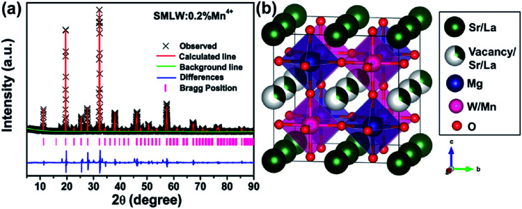
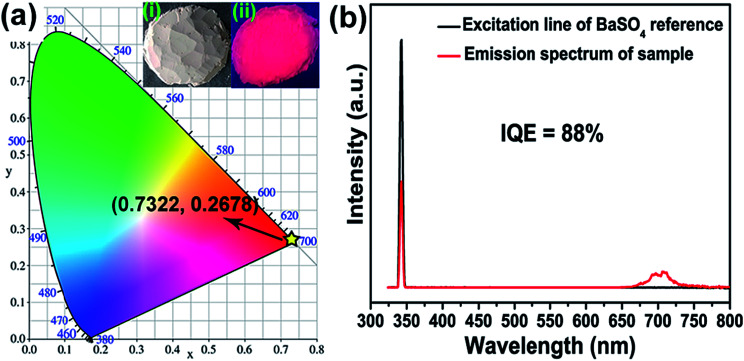
Novel Mn4+-activated far-red emitting SrMg2La2W2O12 (SMLW) phosphors were prepared by a conventional high-temperature solid-state reaction method. The SMLW:Mn4+ phosphors showed a broad excitation band peaking at around 344 nm and 469 nm in the range of 300-550 nm. Under 344 nm near-ultraviolet light or 469 nm blue light, the phosphors exhibited a far-red emission band in the 650-780 nm range centered at about 708 nm. The optimal Mn4+ doping concentration in the SMLW host was 0.2 mol% and the CIE chromaticity coordinates of SMLW:0.2% Mn4+ phosphors were calculated to be (0.7322, 0.2678). In addition, the influences of crystal field strength and nephelauxetic effect on the emission energy of Mn4+ ions were also investigated. Moreover, the internal quantum efficiency of SMLW:0.2% Mn4+ phosphors reached as high as 88% and they also possessed good thermal stability. Specifically, the emission intensity at 423 K still maintained about 57.5% of the initial value at 303 K. Finally, a far-red light-emitting diode (LED) lamp was fabricated by using a 365 nm near-ultraviolet emitting LED chip combined with the as-obtained SMLW:0.2% Mn4+ far-red phosphors.
This journal is © The Royal Society of Chemistry.
Conflict of interest statement
There are no conflicts to declare.
Figures


References
-
- Cao R. Ye Y. Peng Q. Zheng G. Ao H. Fu J. Guo Y. Guo B. Dyes Pigm. 2017;146:14–19. doi: 10.1016/j.dyepig.2017.06.061. - DOI
-
- Cao R. Shi Z. Quan G. Chen T. Guo S. Hu Z. Liu P. J. Lumin. 2017;188:577–581. doi: 10.1016/j.jlumin.2017.05.002. - DOI
-
- Huang X. Guo H. Dyes Pigm. 2018;152:36–42. doi: 10.1016/j.dyepig.2018.01.022. - DOI
-
- Yang C. Zhang Z. Hu G. Cao R. Liang X. Xiang W. J. Alloys Compd. 2017;694:1201–1208. doi: 10.1016/j.jallcom.2016.10.162. - DOI
-
- Cao R. Zhang J. Wang W. Hu Z. Chen T. Ye Y. Yu X. Mater. Res. Bull. 2017;87:109–113. doi: 10.1016/j.materresbull.2016.11.031. - DOI
LinkOut - more resources
Full Text Sources