Review
. 2018 Oct 3;8(59):34012-34034.
doi: 10.1039/c8ra06132g. eCollection 2018 Sep 28.

The potential of paper-based diagnostics to meet the ASSURED criteria

Affiliations
Review

The potential of paper-based diagnostics to meet the ASSURED criteria

Suzanne Smith et al. RSC Adv. .

Erratum in

Abstract

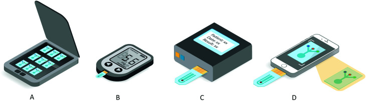
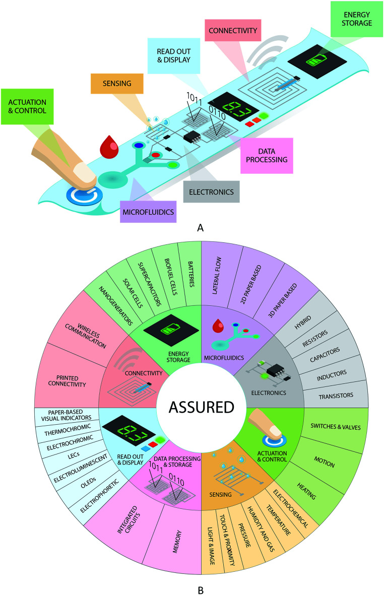
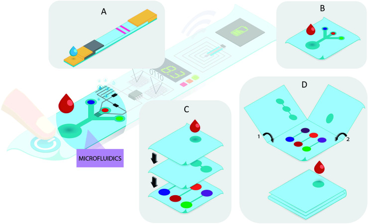
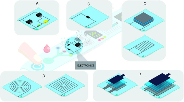
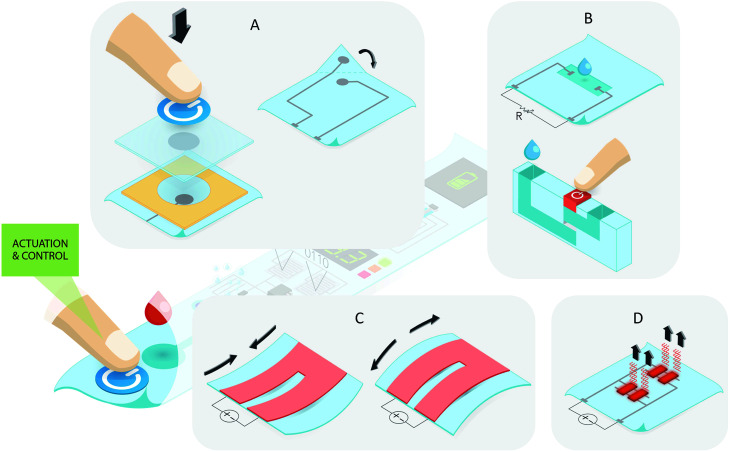
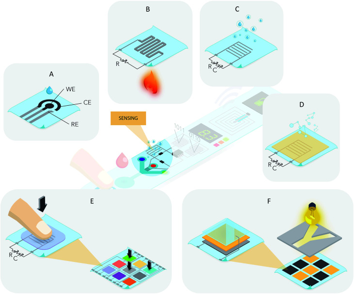
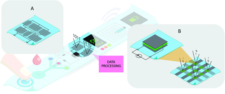
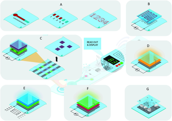
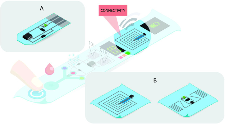
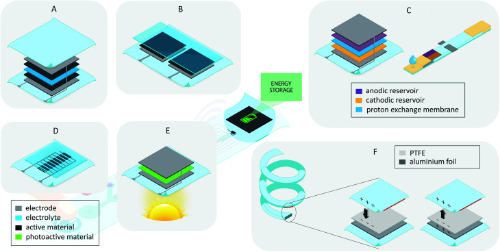
Paper-based diagnostics have already revolutionized point-of-care approaches for health and environmental applications, by providing low-cost, disposable tools that can be utilized in remote settings. These devices typically consist of microfluidic, chemical, and biological diagnostic components implemented on paper substrates, towards addressing the ASSURED (Affordable, Sensitive, Specific, User friendly, Rapid and Robust, Equipment free and Deliverable to end users) principles set out by the World Health Organization. Paper-based diagnostics primarily contribute to the affordable, equipment-free, and deliverable-to-end-user aspects. However, additional functionality must be integrated with paper-based diagnostic devices to achieve truly ASSURED solutions. Advances in printed electronics provide a fitting foundation for implementing augmented functionality, while maintaining the affordability and disposability of paper-based diagnostics. This paper reviews the printed functional building blocks that contribute towards achieving this goal, from individual printed electronic components to fully integrated solutions. Important modules for sensing, read-out of results, data processing and communication, and on-board power are explored, and solutions printed on flexible or paper-based substrates for integration with paper-based diagnostics are considered. Although many of the unit operations required to achieve the ASSURED criteria can be implemented using paper, basic system functionality is still lacking, and this requires a concerted effort in integration of the various components for truly ASSURED solutions to be realized. Beyond ASSURED, modern clinical practises and crisis readiness also require additional informational functionality, which a systems approach using paper-based solutions could ensure.


Conflict of interest statement

There are no conflicts of interest to declare.

Figures

Fig. 1
Fig. 1. Examples of existing external instrumentation solutions that can be used with paper-based diagnostic tests. (A) a desktop scanner, (B) a portable glucose meter used with custom made paper-based diagnostic electrochemical sensors, (C) a custom-made instrument for analysis of paper-based diagnostic test devices, and (D) a phone camera for image capture and processing of a paper-based device and/or for physical connection and analysis of a paper-based device.
Fig. 2
Fig. 2. (A) Envisaged integrated ASSURED device with various functional modules indicated, and (B) graphical summary of the review highlighting the printed functionalities that can be utilized to realize integrated, ASSURED devices.
Fig. 3
Fig. 3. Microfluidics and sample processing functional modules, illustrating typical paper-based diagnostic test formats. (A) Standard lateral flow test strips with sample pad, conjugate pad, test and control lines and wicking pad, (B) two-dimensional paper-based diagnostics using hydrophobic fluidic barriers (e.g. wax printing), and three-dimensional paper-based diagnostics implemented using (C) stacking of multiple layers or (D) folding or origami paper devices for enhanced fluidic control and multiplexing.
Fig. 4
Fig. 4. Printed paper-based electronics. (A) Hybrid printed electronics with surface mount components such as ICs and LEDs, mounted on to printed circuit tracks on paper. (B) Printed resistor with silver tracks and a resistive material to connect the terminals and create a resistive element. (C) Printed capacitor structures, showing both stacked and interdigitated formats. A dielectric material is printed between two conductive electrodes in the stacked format. (D) Printed inductor design with conductive tracks printed in circular or square spiral shapes. (E) Printed transistor with various functional layers labelled (left) and a typical printed transistor layout (right).
Fig. 5
Fig. 5. Paper-based functional components for actuation and control. Switches and valves are illustrated for both (A) electronic and (B) fluidic set ups. (A) Paper-based push buttons, which when pressed, compress a spacer, create contact and close a switch. Fold-over paper designs to make electrical connections and close a switch can also be used. (B) For fluidic implementations, ionic fluids can be introduced to create an electrical pathway, closing a switch, and three-dimensional stacked paper structures with spacers, fluidic channels and buttons can be used to implement paper-based fluidic switches, with a cross-sectional view illustrating this. (C) Movement can be implemented through printing of functional inks which when subjected to voltage and temperature changes, undergo compression or expansion to create motion. (D) Heating on paper using positive temperature coefficient (PTC) inks. These functional inks increase in temperature in response to an applied voltage and self-regulate at a designed temperature for constant and controlled heating.
Fig. 6
Fig. 6. Printed and paper-based sensing functional modules. (A) electrochemical sensors with working electrode (WE), counter electrode (CE) and reference electrodes (RE) indicated. Conductive materials are used for the connections and RE, while WE and CE consist of printed electrochemical functional materials. (B) Temperature sensors, with printed conductive materials and printed temperature sensitive material which varies in resistance as the temperature changes. (C) Humidity sensors, utilizing printed conductive tracks typically in an interdigitated format, which vary in resistance or capacitance as the moisture content changes. (D) Gas sensors, with a similar structure to humidity sensors but with a printed gas sensing material coating the conductive tracks. (E) Pressure, touch and proximity sensors, typically with printed pressure sensitive material over conductive tracks which varies with resistance and/or capacitance in response to pressure. These individual sensors can be implemented in matrix format to realize touch sensors. (F) Light sensors with a printed conductive electrode (bottom), printed photosensitive material (middle) and printed transparent electrode (top). These photodetector elements can also be implemented in matrix format to realize image sensors.
Fig. 7
Fig. 7. Printed data processing and storage functionality. (A) Printed integrated circuits and processors, typically constructed from various printed transistor combinations. (B) Memory components, with individual printed units constructed from printed conductive electrodes with a resistive switching material in between. When implemented in a matrix format, a printed conductive electrode matrix can be implemented, with individual printed resistive switching pixels which can each be set to 1 or 0 values by applying positive or negative voltages, respectively.
Fig. 8
Fig. 8. Printed and paper-based read out and display module examples. (A) Paper-based microfluidic visual indicators, which can be distance or time based, counting based or text based, utilizing the sample and resulting flow or reactions to provide user feedback on the test progress and results. (B) Printed thermochromic displays where applying a voltage to conductive elements covered by a printed thermochromic material results in a colour change in response to a temperature increase. (C) Printed electrochromic displays, with individual pixels made up of printed layers on top of paper as follows: conductive electrode, electroactive material, electrolyte, electrochromic material, and a transparent electrode on top. Applying a voltage causes the electrochromic material to change colour. Pixels can be implemented in matrix format to enable effective text displays. (D) Printed light-emitting electrochemical cells consist of an active material between two electrodes, with the top electrode (cathode) being transparent. Light is emitted by the active material in response to a voltage applied across the electrodes. (E) Electroluminescent displays, with individual units consisting of a conductive electrode on the paper substrate, followed by a printed dielectric layer, a phosphor material and a top transparent electrode. Light is emitted in response to an electric field. (F) Organic light-emitting diodes (OLEDs) consist of two electrodes with a conductive material and an emissive electroluminescent material in between. The latter emits light through the top transparent electrode in response to a current applied at the electrodes. (G) Electrophoretic displays consist of charged black and white particles that change orientation in response to an applied electric field.
Fig. 9
Fig. 9. Printed paper-based connectivity modules. (A) Physical printed connectors on a paper-based electronic device to connect to standard ports or adapters. (B) Wireless connectivity through printed NFC and RFID tags, which can also be integrated with microfluidics.
Fig. 10
Fig. 10. Printed energy storage modules. Batteries can be either in stacked or parallel formats. (A) In a stacked configuration, a paper-based separator soaked with electrolyte is sandwiched between an anode and cathode, each printed on to a current collector on a paper substrate. (B) In a parallel format, two current collectors are printed side by side on a paper substrate, one with an anode material printed on top and one with cathode material. An electrolyte layer is printed or applied over these to complete the battery. (C) Biofuel cells can also utilize a stacked configuration with two electrodes on the outside and anodic and cathodic reservoirs on either side of a proton exchange membrane. Biofuel cells can also be implemented in a lateral flow format, where fuel (anolyte and catholyte) are spotted on to the test and electrodes make contact, completing the cell when water is added to the test strip. (D) Supercapacitors can have either a stacked format – similar to batteries – or an interdigitated configuration with active material over the electrodes and a printed electrolyte layer covering this. (E) Solar cells have a photoactive material between a cathode and anode, printed on to paper or a transparent electrode through which sunlight is absorbed to generate power. (F) Nanogenerators utilize stretching or twisting of paper structures to generate energy. As an example, layers of polytetrafluoroethylene (PTFE) and aluminium foil on paper can be used to generate energy through contact and release of the paper surface to the PTFE surface.
None
Suzanne Smith
None
Jan G. Korvink
None
Dario Mager
None
Kevin Land

Similar articles

Cited by

References

    1. Mabey D. Peeling R. W. Ustianowski A. Perkins M. D. Nat. Rev. Microbiol. 2004;2:231–240. doi: 10.1038/nrmicro841. - DOI - PubMed
    1. Yamada K. Shibata H. Suzuki K. Citterio D. Lab Chip. 2017;17:1206–1249. doi: 10.1039/C6LC01577H. - DOI - PubMed
    1. Yetisen A. K. Akram M. S. Lowe C. R. Lab Chip. 2013;13:2210–2251. doi: 10.1039/C3LC50169H. - DOI - PubMed
    1. Chang J. S. Facchetti A. F. Reuss R. IEEE Journal on Emerging and Selected Topics in Circuits and Systems. 2017;7:7–26.
    1. Khan S. Lorenzelli L. Dahiya R. S. IEEE Sens. J. 2015;15:3164–3185.