. 2022 Apr 28;12(9):1507.
doi: 10.3390/nano12091507.

Microwave-Assisted Synthesis of Reduced Graphene Oxide with Hollow Nanostructure for Application to Lithium-Ion Batteries

Affiliations

Microwave-Assisted Synthesis of Reduced Graphene Oxide with Hollow Nanostructure for Application to Lithium-Ion Batteries

Minseop Lee et al. Nanomaterials (Basel). .

Abstract

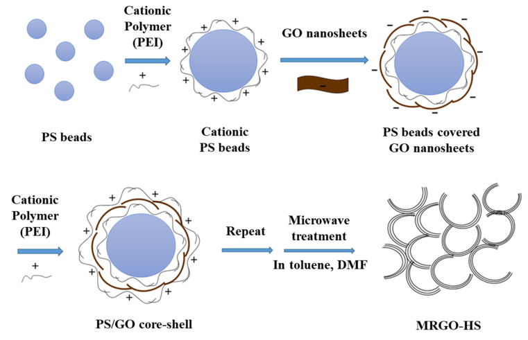
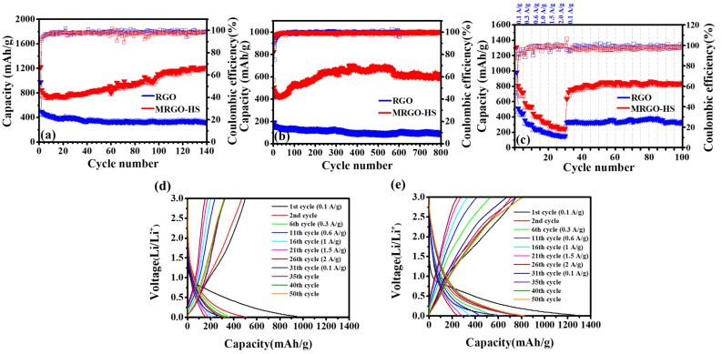
In this study, reduced graphene oxide (RGO) with a hollow nanostructure was successfully synthesized by layer-by-layer self-assembly using electrostatic interactions and van der Waals forces between building blocks, and its lithium storage characteristics were investigated. After 800 cycles at a current density of 1 A/g, the microwave-irradiated RGO hollow spheres (MRGO-HS) maintained a capacity of 626 mA h/g. In addition, when the charge/discharge capacity was measured stepwise in the current density range of 0.1-2 A/g, the discharge capacity of the RGO rapidly decreased to 156 mA h/g even at the current density of 2 A/g, whereas MRGO-HS provided a capacity of 252 mA h/g. Even after the current density was restored at a current density of 0.1 A/g, the MRGO-HS capacity was maintained to be 827 mA h/g at the 100th cycle, which is close to the original reversible capacity. Thus, MRGO-HS provides a higher capacity and better rate capability than those of traditionally synthesized RGO.

Keywords: Exfoliation; hollow spheres; layer-by-layer self-assembly; lithium-ion batteries; reduced graphene oxide.


Conflict of interest statement

The authors declare no conflict of interest. And the funders had no role in the design of the study; in the collection, analyses, or interpretation of data; in the writing of the manuscript; or in the decision to publish the results.

Figures

Figure 1
Figure 1
Schematic illustration of the MRGO-HS synthesis.
Figure 2
Figure 2
XRD patterns of (a) graphene oxide (GO), (b) reduced GO (RGO), (c) MRGO-HS, (d) PS beads, and (e) PS/GO core–shell.
Figure 3
Figure 3
SEM images of the (a,b) PS beads, (c,d) PS/GO core–shell, and (e,f) MRGO-HS.
Figure 4
Figure 4
TEM images of (ac) MRGO-HS. (d) HRTEM image of MRGO-HS with the multi-layer structure indicated by the red line.
Figure 5
Figure 5
Brightness profile of the red lines in Figure 4d.
Figure 6
Figure 6
FTIR spectra of (a) GO, (b) RGO, (c) MRGO-HS, (d) PS beads, and (e) PS/GO core–shell.
Figure 7
Figure 7
The Raman spectra of GO, RGO, and MRGO-HS.
Figure 8
Figure 8
C 1s and O 1s core level X-ray photoemission spectra of the (a,b) GO, (c,d) RGO, and (e,f) MRGO-HS samples. The table below the spectra shows the atomic percentages of C, O, and N in GO, RGO, and MRGO-HS in the XPS analysis.
Figure 9
Figure 9
N2 adsorption/desorption isotherms of GO and MRGO-HS. The inset image is the pore size distribution curves of MRGO-HS.
Figure 10
Figure 10
TGA curves of MRGO-HS and GO.
Figure 11
Figure 11
(a) Cycling performance and coulombic efficiency of RGO and MRGO-HS (at the current density of 0.1 A/g), (b) at the current density of 1 A/g, (c) at various current densities. Galvanostatic charge/discharge curves of (d) RGO, and (e) MRGO-HS between 0.01 and 3.0 V at various current densities.
Figure 12
Figure 12
(a) Nyquist plots for a fresh cell and (b) Nyquist plots after 70 cycles. Warburg plots for a fresh cell (c) and after 70 cycles (d).
Figure 13
Figure 13
Area covered under the CV curves of (a) MRGO-HS and (b) RGO.
Figure 14
Figure 14
CV curves of (a) MRGO-HS and (b) RGO at different scan rates. (c) The log(i) versus log(v) plots of MRGO-HS and RGO. Pseudocapacitive (blue area) and diffusion (red area) contribution to the charge storage of (d) MRGO-HS and (e) RGO at 0.8 mV/s. (f) Proportion of pseudocapacitive contribution at different scan rates of MRGO-HS and RGO.

Similar articles

Cited by

References

    1. Qin J., He C., Zhao N., Wang Z., Shi C., Liu E.-Z., Li J. Graphene Networks Anchored with Sn@Graphene as Lithium Ion Battery Anode. ACS Nano. 2014;8:1728–1738. doi: 10.1021/nn406105n. - DOI - PubMed
    1. Jeong J.M., Choi B.G., Lee S.C., Lee K.G., Chang S.J., Han Y.K., Lee Y.B., Lee H.U., Kwon S., Lee G. Hierarchical Hollow Spheres of Fe2O3@Polyaniline for Lithium Ion Battery Anodes. Adv. Mater. 2013;25:6250–6255. doi: 10.1002/adma.201302710. - DOI - PubMed
    1. Peng K., Jie J., Zhang W., Lee S.-T. Silicon nanowires for rechargeable lithium-ion battery anodes. Appl. Phys. Lett. 2008;93:033105. doi: 10.1063/1.2929373. - DOI
    1. Yoo E., Kim J., Hosono E., Zhou H.-S., Kudo T., Honma I. Enhanced Cyclic Performance and Lithium Storage Capacity of SnO2/Graphene Nanoporous Electrodes with Three-Dimensionally Delaminated Flexible Structure. Nano Lett. 2008;8:2277–2282. doi: 10.1021/nl800957b. - DOI - PubMed
    1. Huang X., Qian K., Yang J., Zhang J., Li L., Yu C., Zhao D. Functional Nanoporous Graphene Foams with Controlled Pore Sizes. Adv. Mater. 2012;24:4419–4423. doi: 10.1002/adma.201201680. - DOI - PubMed

LinkOut - more resources