. 2022 Apr 20;14(9):1670.
doi: 10.3390/polym14091670.

Reactive Cellu-mers-A Novel Approach to Improved Cellulose/Polymer Composites

Affiliations

Reactive Cellu-mers-A Novel Approach to Improved Cellulose/Polymer Composites

Dariya Getya et al. Polymers (Basel). .

Abstract

In this paper, we describe a novel method for preparation of polymer composites with homogeneous dispersion of natural fibers in the polymer matrix. In our approach, Williamson ether synthesis is used to chemically modify cellulose with polymerizable styrene moieties and transform it into a novel multifunctional cellu-mer that can be further crosslinked by copolymerization with styrene. Reactions with model compounds (cellobiose and cellotriose) successfully confirm the viability of the new strategy. The same approach is used to transform commercially available cellulose nanofibrils (CNFs) of various sizes: Sigmacell and Technocell™ 40, 90 and 150. The styrene-functionalized cellulose oligomers and CNFs are then mixed with styrene and copolymerized in bulk at 65 °C with 2,2'-azobisisobutyronitrile as initiator. The resulting composites are in a form of semi-interpenetrating networks (s-IPN), where poly(styrene) chains are either crosslinked with the uniformly dispersed cellulosic component or entangled through the network. Non-crosslinked poly(styrene) (31-41 w%) is extracted with CHCl3 and analyzed by size-exclusion chromatography to estimate the extent of homopolymerization and reveal the mechanism of the whole process. Electron microscopy analyses of the networks show the lack of cellu-mer agglomeration throughout the polymer matrix. The homogeneous distribution of cellulose entities leads to improved thermal and mechanical properties of the poly(styrene) composites compared to the physical mixtures of the same components and linear poly(styrene) of similar molecular mass.

Keywords: cellulose nanofibrils; copolymerization; polymer nanocomposites; polystyrene; semi-interpenetrating networks.


Conflict of interest statement

The authors declare no conflict of interest.

Figures

Scheme 1
Scheme 1
Surface modification of CNF and subsequent copolymerization with St.
Figure 1
Figure 1
Schematic representation of PSt semi-interpenetrating network formed by copolymerization of modified cellobiose and St.
Scheme 2
Scheme 2
Tentative modification of cellobiose via Williamson ether synthesis.
Figure 2
Figure 2
MALDI-TOF spectra of cellobiose modified with eight equivalents of 4-VBC at 25 °C. (a) neat cellobiose; (b) modified cellobiose after 5 h; (c) modified cellobiose after 22 h. DHB was used as a matrix.
Figure 3
Figure 3
IR spectra of cellobiose before and after the 4-VBC modification: (A) 4-VBC; (B) neat cellobiose; (C) cellobiose modified with six equivalents of 4-VBC (cellobiose-m).
Figure 4
Figure 4
Number of 4-VBC groups attached to 1 g of Sigmacell depending on equivalents of 4-VBC used. Calculated by measuring the UV absorption of DMSO suspensions at 265 nm.
Figure 5
Figure 5
IR spectra of cellulose modification reaction: (A) 4-VBC; (B) neat Sigmacell; (C) Sigmacell-m.
Figure 6
Figure 6
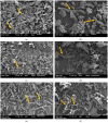
Scanning electron micrographs of cellulose fibers. Orange arrows point on the cellulose fibers, where surface morphology is especially noticeable. Working distance 11 mm, objective aperture (OA) 1. (a) Sigmacell not modified, magnification 600×; (b) Sigmacell modified, magnification 600×; (c) T-40 not modified, magnification 200×; (d) T-40 modified, magnification 200×; (e) T-90 not modified, magnification 200×; (f) T-90 modified, magnification 200×; (g) T-150 not modified, magnification 200×; (h) T-150 modified, magnification 200×.
Figure 6
Figure 6
Scanning electron micrographs of cellulose fibers. Orange arrows point on the cellulose fibers, where surface morphology is especially noticeable. Working distance 11 mm, objective aperture (OA) 1. (a) Sigmacell not modified, magnification 600×; (b) Sigmacell modified, magnification 600×; (c) T-40 not modified, magnification 200×; (d) T-40 modified, magnification 200×; (e) T-90 not modified, magnification 200×; (f) T-90 modified, magnification 200×; (g) T-150 not modified, magnification 200×; (h) T-150 modified, magnification 200×.
Figure 7
Figure 7
Surface wettability test of not modified (1) and modified (2) cellulose fibers: (a) Sigmacell; (b) T-40; (c) T-90; (d) T-150.
Figure 7
Figure 7
Surface wettability test of not modified (1) and modified (2) cellulose fibers: (a) Sigmacell; (b) T-40; (c) T-90; (d) T-150.
Figure 8
Figure 8
Swelling degree (SD, %) of the cellobiose-m gels with different components ratio of cellobiose-m/styrene/AIBN. (A) 1/100/0.5; (B) 1/50/0.5; (C) 1/20/0.5.
Figure 9
Figure 9
Scanning electron micrographs of PSt composites formed with Sigmacell-m: (a) Sample swollen in chloroform and then cryo-fractured. Working distance 11 mm, OA 1, magnification 1000×; (b) Sample cryo-fractured in dry state. Working distance 14 mm, OA 1, magnification 550×.
Figure 10
Figure 10
Surface morphology of a T-40 mixture ((a,c), magnification 40×; and 90×; respectively) and T-40-m composite specimen ((b,d), magnification 40×; and 90×, respectively). Working distance 25 mm, OA 1, AV 10 kV, P.C. 50.
Figure 11
Figure 11
Transmission electron micrographs of Sigmacell-based semi-IPN, stained with 2% uranyl acetate: (a) Magnification 800×; (b) Magnification 6000×. Red arrows mark visible cellulose fibers.
Figure 12
Figure 12
DMA thermograms of tested samples: (a) Storage modulus E′, (b) Loss modulus E″, (c) Tan δ. (1) PSt, (2) composite prepared with Sigmacell-m, (3) physical Sigmacell/PSt mixture.
Figure 13
Figure 13
DMA thermograms of tested samples. (a) Storage modulus E′ of poly(styrene), (b) Loss modulus E″, (c) Tan δ of (1) poly(styrene), (2) T-40 composite, (3) T-90 composite and (4) T-150 composite.

References

    1. Rajak D.K., Pagar D.D., Menezes P.L., Linul E. Fiber-reinforced polymer composites: Manufacturing, properties, and applications. Polymers. 2019;11:1667. doi: 10.3390/polym11101667. - DOI - PMC - PubMed
    1. Tatar J., Milev S. Durability of externally bonded fiber-reinforced polymer composites in concrete structures: A critical review. Polymers. 2021;13:765. doi: 10.3390/polym13050765. - DOI - PMC - PubMed
    1. Hetzer M., De Kee D. Wood/polymer/nanoclay composites, environmentally friendly sustainable technology: A review. Chem. Eng. Res. Des. 2008;86:1083–1093. doi: 10.1016/j.cherd.2008.05.003. - DOI
    1. Stadlmann A., Mautner A., Pramreiter M., Bismark A., Müller U. Interfacial Adhesion and Mechanical Properties of Wood-Polymer Hybrid Composites Prepared by Injection Moulding. Polymers. 2021;13:2849. doi: 10.3390/polym13172849. - DOI - PMC - PubMed
    1. Klemm D., Heublein B., Fink H.P., Bohn A. Cellulose: Fascinating biopolymer and sustainable raw material. Angew. Chem. Int. Ed. Engl. 2005;44:3358–3393. doi: 10.1002/anie.200460587. - DOI - PubMed

LinkOut - more resources