Review
. 2022 May 29:1209:339842.
doi: 10.1016/j.aca.2022.339842. Epub 2022 Apr 30.

Applied tutorial for the design and fabrication of biomicrofluidic devices by resin 3D printing

Affiliations
Review

Applied tutorial for the design and fabrication of biomicrofluidic devices by resin 3D printing

Hannah B Musgrove et al. Anal Chim Acta. .

Abstract

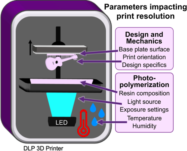
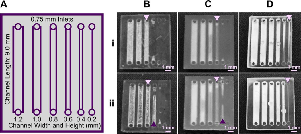
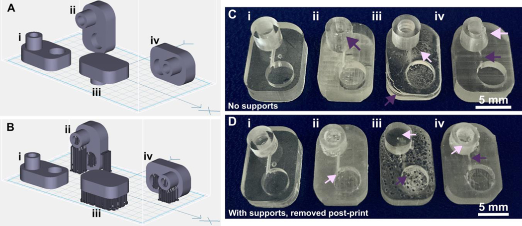
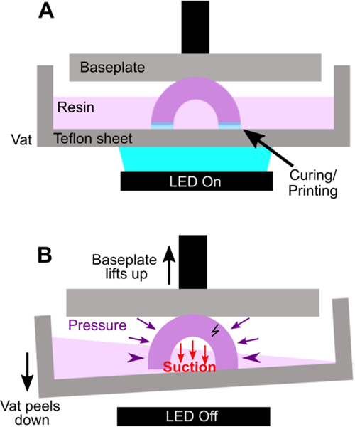
Resin 3D printing, especially digital light processing (DLP) printing, is a promising rapid fabrication method for bio-microfluidic applications such as clinical tests, lab-on-a-chip devices, and sensor integrated devices. The benefits of 3D printing lead many to believe this fabrication method will accelerate the use of microfluidics, but there are a number of potential obstacles to overcome for bioanalytical labs to fully utilize this technology. For commercially available printing materials, this includes challenges in producing prints with the print resolution and mechanical stability required for a particular design, along with cytotoxic components within many photopolymerizing resins and low optical compatibility for imaging experiments. Potential solutions to these problems are scattered throughout the literature and rarely available in head-to-head comparisons. Therefore, we present here a concise guide to the principles of resin 3D printing most relevant for fabrication of bioanalytical microfluidic devices. Intended to quickly orient labs that are new to 3D printing, the tutorial includes the results of selected systematic tests to inform resin selection, strategies for design optimization, and improvement of biocompatibility of resin 3D printed bio-microfluidic devices.

Keywords: Cell culture; Digital light processing; Microfluidic fabrication; Photopolymerizable resins; SLA; Stereolithography.


Conflict of interest statement

Conflict of interest statement

The authors have no conflicting interests to declare.

Figures

Fig. 1.
Fig. 1.
Schematic of a DLP 3D printer, highlighting the design and mechanical factors as well photopolymerization parameters which influence print resolution. Digital light processing 3D printers project UV or violet light through optically clear sheets (usually Teflon) into a vat of photopolymerizable resin (pink). In locations where the light is projected, the resin crosslinks to form a solid structure. Exposure and crosslinking are performed layer by layer on the base plate, which lifts up as each concurrent layer is formed. Production of a clean print is dependent on instrumental, environmental, chemical, and design elements that impact either the print surface (base plate), mechanics (print orientation, design specifics), or chemical reaction (resin composition, light source, exposure settings, temperature, or humidity).
Fig. 2.
Fig. 2.
The resolution of internal features can be increased by making changes to the light source, resin viscosity, and print layer height. (A) A test piece had six internal channels, 9-mm long with 0.75 mm diameter inlets and varied channel cross-sections as noted. It was printed with (B-D) (i) 50 μm layer height or (ii) 100 μm layer height, as follows: FormLabs Clear resin was printed with a (B) 405 nm or (C) 385 nm light source; (D) for comparison, a low viscosity resin, BV007a, was printed at 385 nm. Other settings were left unchanged, with the exception of increasing exposure times slightly for some 100-μm prints (Table S1). Resolution was determined visually by observing the smallest channel cross-section that could be printed fully (pink arrows) or partially open (purple arrows).
Fig. 3.
Fig. 3.
Orientation of prints on a build plate impacts the print resolution and optical clarity. A microfluidic design containing a reservoir, channel, and chamber is shown in the MiiCraft Utility slicing software in four orientations (A) without supports and (B) with supports: (i) base-down, (ii) vertical, (iii) top-down, and (iv) horizontal. Blue grid represents the base plate. Supports were added to all areas using default settings in the slicing software. (C, D) Photos of pieces printed in BV007a resin with the MiiCraft Ultra 50 printer, (C) printed without supports, and (D) printed with supports, with 2 minutes of support removal. Surface roughness and clarity variation is evident between the 4 orientations. Defects were noted as follows: In C: (i) no defects, (ii) overhang drooping, (iii) delamination (purple) and stress fracturing (pink), (iv) blocked channel (purple), overhang drooping (pink); in D: (i) no defects, (ii) stress fracturing, (iii) damage from supports (purple) and filled chamber (pink), (iv) filled channel (purple) and support damage (pink).
Fig. 4.
Fig. 4.
Schematic of “cupping” damage during the printing of a hollow, cup-like feature. (A) During printing, a UV light source (LED) forms a new crosslinked layer of resin flush against the teflon sheet. This design is an inverted bowl shape; supports are not shown for clarity. (B) After a layer is finished printing, the print is peeled away from the teflon sheet, e.g. by pulling the vat down and/or the baseplate up. This process creates a region of suction within the hollow cup feature; the surrounding pressure, now higher than the pressure within piece, may form a stress fracture on the print.
Fig. 5.
Fig. 5.
Strengthening the design around well-like features decreases the impacts of cupping and resin shrinkage. (i) Illustrated computer-aid designs, and (ii) photos of the top and bottom views of the corresponding print. All pieces were printed in FormLabs Clear resin. Well A had thin walls, thin base, and strain from 90° connections at the bases and the sides. Well B had thicker surrounding walls and a thicker, filleted base, but retained 90° outer corners. Wells C and D further reduced the strain by rounding out the external edges. All pieces were qualitatively evaluated, with the absence of cracks (arrowheads) and pinholes (shown by arrows) indicating a strong design.
Fig.6.
Fig.6.
Reducing the number of overhang layers in the chip design improved the resolution of internal features. (A) Schematic of the test piece with six internal channels, in (i) top view and (ii) side view. (B,C) Channels were printed with (B) 1.5 mm or (C) 0.5 mm overhang thickness, and imaged from (i) top and (ii) side. The square channel is traced with dashed outlines; the features visible above the channel in the side view are inlets and outlets. All pieces were printed in FL Clear resin with a 405 nm light source (settings in Table S1). Resolution was determined visually by observing the smallest channel cross-section that could be printed fully (pink arrows).
Fig. 7.
Fig. 7.
Viability of primary murine splenocytes in contact with 3D printed materials. Primary splenocytes from male and female mice (Nmice = 2 per experiment) were evaluated by flow cytometry after live/dead staining with Calcein-AM/7AAD. (A) Cell viability after 4 hr of direct physical contact with PBS+incubation treated (T) or non-treated (N) resins compared with well plate control (C). Treated BioMed and Clear prints maintained relatively high viability compared to the well plate, while BV007 did not. Bars show mean ± SD. One-way ANOVA per data set, ns > 0.06, *p > 0.01, **p = 0.01, ****p < 0.0001. (B) Multiple post-treatment methods (PBS, incubation at 37 °C, PBS+incubation, and autoclavation) were evaluated using BioMed resin and culturing for 4 hours with direct contact. Bars show mean ± SD. One-way ANOVA, ns > 0.2, *p > 0.02. ****p < 0.0001. (C) Viability of direct contact (i.e. culture with resin) and indirect contact (i.e. culture with resin leachate) of cells with treated BioMed prints at 45 min, 4 hours, and 24 hours showed a decrease in viability over time. Values show mean ± SD. One-way ANOVA at final time point, ****p < 0.0001.
Fig. 8.
Fig. 8.
Autofluorescence depended on resin composition and fluorescence filter set. BioMed, Clear, and BV007a prints were evaluated in comparison to PDMS for autofluorescence in Cy5, Rhodamine, EGFP, and DAPI fluorescent channels. Background subtracted mean grey values were analyzed with ImageJ and used to determine the fluorescent intensity of each material. Saturation values were at 65,000 AU. Bars show mean ± SD, N=3 intensity measurements per print. Two-way ANOVA, comparisons shown between resin results versus PDMS for each respective fluorescent channel, ****p<0.0001.
Fig.9.
Fig.9.
Optical clarity of clear resins was enhanced with post-treatments that achieved material transparency similar to glass. Round prints of FormLabs Clear resin were printed with the MiiCraft Ultra 50 405 printer and post-treated as listed in the legend, labels II -VII. (A) The test pieces were positioned over the Pompano Lab logo for qualitative, visual comparison (captured with phone camera). (B) Transmittance was evaluated using an upright microscope. Relative transmittance was compared to the average light transmittance through a 0.17 mm thick glass slide (I). Bars show mean ± standard deviation, n = 3. One-way ANOVA, Tukey’s post-hoc test; *p = 0.0284, **p = 0.0067, and ns > 0.05. (C) To show reproducibility for different resins, technique II was applied to similar round prints in FL BioMed, FL Clear, and MC BV007a resins and evaluated similarly to panel B. All nail polished samples were statistically similar compared to the glass slide control. Two-way ANOVA, Tukey’s multiple comparison test; ***p=0.0003, ****p<0.0001, and ns>0.8.

Similar articles

Cited by

References

    1. Morbioli GG; Speller NC; Stockton AM A Practical Guide to Rapid-Prototyping of PDMS-Based Microfluidic Devices: A Tutorial. Anal. Chim. Acta 2020, 1135, 150–174. 10.1016/j.aca.2020.09.013. - DOI - PubMed
    1. Torino S; Corrado B; Iodice M; Coppola G PDMS-Based Microfluidic Devices for Cell Culture. Inventions 2018, 3 (3), 65. 10.3390/inventions3030065. - DOI
    1. Zhang C; Bills BJ; Manicke NE Rapid Prototyping Using 3D Printing in Bioanalytical Research. Bioanalysis 2017, 9 (4), 329–331. 10.4155/bio-2016-0293. - DOI - PubMed
    1. Dirkzwager RM; Liang S; Tanner JA Development of Aptamer-Based Point-of-Care Diagnostic Devices for Malaria Using Three-Dimensional Printing Rapid Prototyping. ACS Sens. 2016, 1 (4), 420–426. 10.1021/acssensors.5b00175. - DOI
    1. Bhattacharjee N; Urrios A; Kang S; Folch A The Upcoming 3D-Printing Revolution in Microfluidics. Lab. Chip 2016, 16 (10), 1720–1742. 10.1039/C6LC00163G. - DOI - PMC - PubMed

LinkOut - more resources