

A neuromuscular model of human locomotion combines spinal reflex circuits with voluntary movements
- PMID: 35581211
- PMCID: PMC9114145
- DOI: 10.1038/s41598-022-11102-1
A neuromuscular model of human locomotion combines spinal reflex circuits with voluntary movements
Abstract
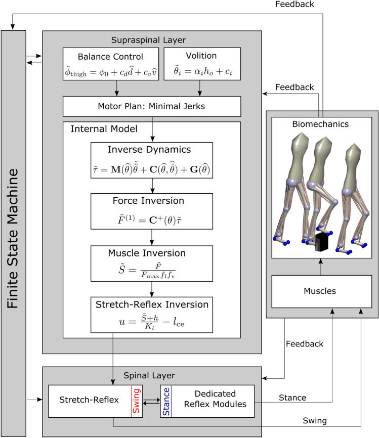
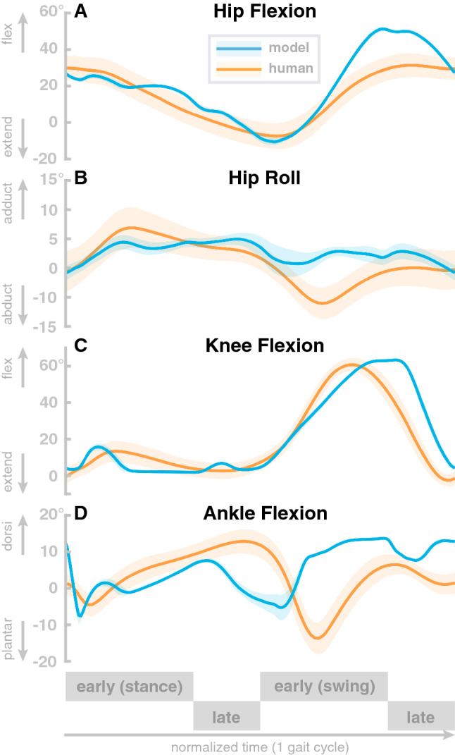
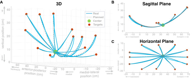
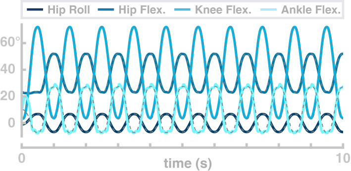
Existing models of human walking use low-level reflexes or neural oscillators to generate movement. While appropriate to generate the stable, rhythmic movement patterns of steady-state walking, these models lack the ability to change their movement patterns or spontaneously generate new movements in the specific, goal-directed way characteristic of voluntary movements. Here we present a neuromuscular model of human locomotion that bridges this gap and combines the ability to execute goal directed movements with the generation of stable, rhythmic movement patterns that are required for robust locomotion. The model represents goals for voluntary movements of the swing leg on the task level of swing leg joint kinematics. Smooth movements plans towards the goal configuration are generated on the task level and transformed into descending motor commands that execute the planned movements, using internal models. The movement goals and plans are updated in real time based on sensory feedback and task constraints. On the spinal level, the descending commands during the swing phase are integrated with a generic stretch reflex for each muscle. Stance leg control solely relies on dedicated spinal reflex pathways. Spinal reflexes stimulate Hill-type muscles that actuate a biomechanical model with eight internal joints and six free-body degrees of freedom. The model is able to generate voluntary, goal-directed reaching movements with the swing leg and combine multiple movements in a rhythmic sequence. During walking, the swing leg is moved in a goal-directed manner to a target that is updated in real-time based on sensory feedback to maintain upright balance, while the stance leg is stabilized by low-level reflexes and a behavioral organization switching between swing and stance control for each leg. With this combination of reflex-based stance leg and voluntary, goal-directed control of the swing leg, the model controller generates rhythmic, stable walking patterns in which the swing leg movement can be flexibly updated in real-time to step over or around obstacles.
© 2022. The Author(s).
Conflict of interest statement
The authors declare no competing interests.
Figures

Similar articles
-
Contributions to the understanding of gait control.Dan Med J. 2014 Apr;61(4):B4823. Dan Med J. 2014. PMID: 24814597 Review.
-
Differential control of reciprocal inhibition during walking versus postural and voluntary motor tasks in humans.J Neurophysiol. 1997 Jul;78(1):429-38. doi: 10.1152/jn.1997.78.1.429. J Neurophysiol. 1997. PMID: 9242291 Clinical Trial.
-
Arm sway holds sway: locomotor-like modulation of leg reflexes when arms swing in alternation.Neuroscience. 2014 Jan 31;258:34-46. doi: 10.1016/j.neuroscience.2013.10.007. Epub 2013 Oct 18. Neuroscience. 2014. PMID: 24144625
-
Neural regulation of rhythmic arm and leg movement is conserved across human locomotor tasks.J Physiol. 2007 Jul 1;582(Pt 1):209-27. doi: 10.1113/jphysiol.2007.133843. Epub 2007 Apr 26. J Physiol. 2007. PMID: 17463036 Free PMC article.
-
What functions do reflexes serve during human locomotion?Prog Neurobiol. 1999 Jun;58(2):185-205. doi: 10.1016/s0301-0082(98)00081-1. Prog Neurobiol. 1999. PMID: 10338359 Review.
Cited by
-
Identifying essential factors for energy-efficient walking control across a wide range of velocities in reflex-based musculoskeletal systems.PLoS Comput Biol. 2024 Jan 19;20(1):e1011771. doi: 10.1371/journal.pcbi.1011771. eCollection 2024 Jan. PLoS Comput Biol. 2024. PMID: 38241215 Free PMC article.
-
Methods for integrating postural control into biomechanical human simulations: a systematic review.J Neuroeng Rehabil. 2023 Aug 21;20(1):111. doi: 10.1186/s12984-023-01235-3. J Neuroeng Rehabil. 2023. PMID: 37605197 Free PMC article.
-
A PRISMA systematic review through time on predictive musculoskeletal simulations.J Neuroeng Rehabil. 2025 Jul 4;22(1):149. doi: 10.1186/s12984-025-01686-w. J Neuroeng Rehabil. 2025. PMID: 40615923 Free PMC article.
-
Gait Environment Recognition Using Biomechanical and Physiological Signals with Feed-Forward Neural Network: A Pilot Study.Sensors (Basel). 2025 Jul 10;25(14):4302. doi: 10.3390/s25144302. Sensors (Basel). 2025. PMID: 40732434 Free PMC article.
-
High-level motor planning allows flexible walking at different gait patterns in a neuromechanical model.Front Bioeng Biotechnol. 2022 Dec 8;10:959357. doi: 10.3389/fbioe.2022.959357. eCollection 2022. Front Bioeng Biotechnol. 2022. PMID: 36568295 Free PMC article.
References
-
- Levine D, Richards J, Whittle MW. Whittle’s Gait Analysis. Amsterdam: Elsevier Health Sciences; 2012.
-
- Inman VT, Ralston HJ, Todd F, Lieberman JC. Human Walking. Philadelphia: Williams & Wilkins; 1981.
Publication types
MeSH terms
LinkOut - more resources
Full Text Sources
Miscellaneous
