Review
. 2022 Apr 26;22(9):3329.
doi: 10.3390/s22093329.

Current Sheet Antenna Array and 5G: Challenges, Recent Trends, Developments, and Future Directions

Affiliations
Review

Current Sheet Antenna Array and 5G: Challenges, Recent Trends, Developments, and Future Directions

Sajjad Hussain et al. Sensors (Basel). .

Abstract

Designing an ultra-wideband array antenna for fifth generation (5G) is challenging for the antenna designing community because of the highly fragmented electromagnetic spectrum. To overcome bandwidth limitations, several millimeter-wave bands for 5G and beyond applications are considered; as a result, many antenna arrays have been proposed during the past decades. This paper aims to explore recent developments and techniques regarding a specific type of phased array antenna used in 5G applications, called current sheet array (CSA). CSA consists of capacitively coupled elements placed over a ground plane, with mutual coupling intentionally introduced in a controlled manner between the elements. CSA concept evolved and led to the realization of new array antennas with multiple octaves of bandwidth. In this review article, we provide a comprehensive overview of the existing works in this line of research. We analyze and discuss various aspects of the proposed array antennas with the wideband and wide-scan operation. Additionally, we discuss the significance of the phased array antenna in 5G communication. Moreover, we describe the current research challenges and future directions for CSA-based phased array antennas.

Keywords: 5G; antenna array; current sheet array (CSA); millimeter-wave; ultra-wideband (UWB).


Conflict of interest statement

The authors declare no conflict of interest.

Figures

Figure 1
Figure 1
Historical perspective and present state of CSA technology.
Figure 2
Figure 2
Advantages of CSA-based array design.
Figure 3
Figure 3
A typical TCDA equivalent circuit.
Figure 4
Figure 4
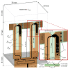
Unit element implemented with an integrated balun, each cell has two 100 Ω baluns fed using a single 50 Ω microstrip trace [38].
Figure 5
Figure 5
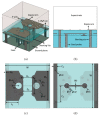
Millimeter-wave array prototype for n257 5G band (a) isometric view unit element Dx, Dy = 5 mm; (b) top view (including meta-surface loaded WAIM layer); (c) bottom view [44].
Figure 6
Figure 6
(a) 8 × 8 planar 5G millimeter-wave array prototype active VSWR; (b) Broadside co-polarized and cross-polarized gain versus frequency [44].
Figure 7
Figure 7
12  ×  12 array prototype designed for 26, 28 GHz 5G millimeter-wave bands (a) top view; (b) bottom view of the ground plane with 64-element [23].
Figure 8
Figure 8
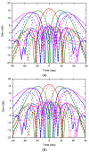
Measured (dashed curve) and simulated (solid curve) scan patterns of 5G millimeter-wave array (32 elements excited) at 26.5 GHz for scan to 0° (red), ±30° (green), ±45° (blue), ±60° (magenta) (a) E-plane; (b) H-plane [23].
Figure 9
Figure 9
Unit cell illustration. From top to bottom: superstrate, overlapping bowtie elements, resistive sheet, ground plane, and 3-stage Wilkinson power divider [56].
Figure 10
Figure 10
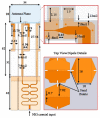
Unit element design of the tightly coupled open folded dipole array [68].
Figure 11
Figure 11
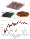
(a) 5 × 5 UWB phased array prototype for millimeter-Wave ISM and 5G bands, without measurement fixtures alongside a U.S. penny. Inset (top): array interior structure; (b) Broadside gain of the 3 × 3 array prototype. Co-polarized (solid curve) and cross-polarized (dashed) [73].
Figure 12
Figure 12
Simulated S21 of the coax to microstrip transition, (a) coax port shifted laterally by 0–0.254 mm); (b) coax port shifted axially by −0.254–0.508 mm [73].
Figure 13
Figure 13
Unit element geometry of fully planar Ultrawideband tightly-coupled array (FPU-TCA), with different views (a) 3-D; (b) cross-sectional; (c) dipole layer; (d) horizontal part of the feed probe [76].
Figure 14
Figure 14
(a) Backside view of fully-planar wide-scan millimeter-wave 8 × 4 array prototype in H-structure for scanning to 45°; (b) Measured S21 of the connector and line and the total value corresponding to the feed networks for the broadside and 45° radiation [76].
Figure 15
Figure 15
Simulated and measured normalized realized gain of 8 × 4 arrays for (a) broadside radiation in E-plane; (b) broadside radiation in H-plane; (c) 45° radiation in E-plane; (d) 45° radiation in H-plane [76].
Figure 16
Figure 16
Geometry of the proposed millimeter-wave circularly polarized arrays unit element (a) 3-D view; (b) Side view [79].
Figure 17
Figure 17
Fabricated prototype, (a) top view; (b) bottom view; (c) testing in the anechoic chamber [79].
Figure 18
Figure 18
Measured and simulated reflection coefficients of the 8 × 8 CP array antenna for millimeter-wave applications [79].
Figure 19
Figure 19
Measured and simulated radiation patterns of 64-element CP millimeter-wave array at (a) 19; (b) 24.5; (c) 30 GHz [79].
Figure 20
Figure 20
Measured and simulated gains and efficiencies of the CP array designed for 24, 26, 28 GHz 5G bands [79].

References

    1. Pi Z., Khan F. An Introduction to Millimeter-Wave Mobile Broadband Systems. IEEE Commun. Mag. 2011;49:101–107. doi: 10.1109/MCOM.2011.5783993. - DOI
    1. Rappaport T.S., Gutierrez F., Ben-Dor E., Murdock J.N., Qiao Y., Tamir J.I. Broadband Millimeter-Wave Propagation Measurements and Models Using Adaptive-Beam Antennas for Outdoor Urban Cellular Communications. IEEE Trans. Antennas Propag. 2013;61:1850–1859. doi: 10.1109/TAP.2012.2235056. - DOI
    1. Marcus M.J. 5G and «iMT for 2020 and Beyond» [Spectrum Policy and Regulatory Issues] IEEE Wirel. Commun. 2015;22:2–3. doi: 10.1109/MWC.2015.7224717. - DOI
    1. Qiao J., Shen X., Mark J., Shen Q., He Y., Lei L. Enabling Device-to-Device Communications in Millimeter-Wave 5G Cellular Networks. IEEE Commun. Mag. 2015;53:209–215. doi: 10.1109/MCOM.2015.7010536. - DOI
    1. Wang C.X., Haider F., Gao X., You X.H., Yang Y., Yuan D., Aggoune H.M., Haas H., Fletcher S., Hepsaydir E. Cellular Architecture and Key Technologies for 5G Wireless Communication Networks. IEEE Commun. Mag. 2014;52:122–130. doi: 10.1109/MCOM.2014.6736752. - DOI

LinkOut - more resources