. 2022 Apr 29;22(9):3409.
doi: 10.3390/s22093409.

Ballistic Deficit Pulse Processing in Cadmium-Zinc-Telluride Pixel Detectors for High-Flux X-ray Measurements

Affiliations

Ballistic Deficit Pulse Processing in Cadmium-Zinc-Telluride Pixel Detectors for High-Flux X-ray Measurements

Antonino Buttacavoli et al. Sensors (Basel). .

Abstract

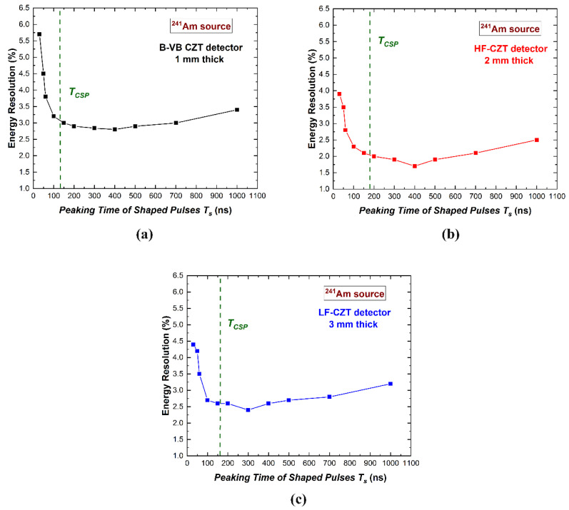
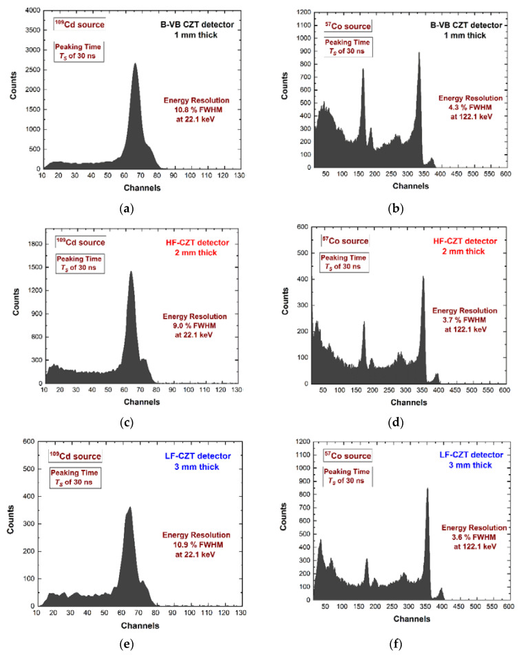
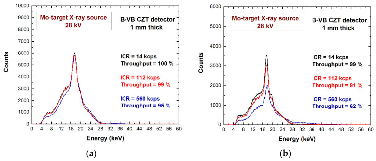
High-flux X-ray measurements with high-energy resolution and high throughput require the mitigation of pile-up and dead time effects. The reduction of the time width of the shaped pulses is a key approach, taking into account the distortions from the ballistic deficit, non-linearity, and time instabilities. In this work, we will present the performance of cadmium−zinc−telluride (CdZnTe or CZT) pixel detectors equipped with digital shapers faster than the preamplifier peaking times (ballistic deficit pulse processing). The effects on energy resolution, throughput, energy-linearity, time stability, charge sharing, and pile-up are shown. The results highlight the absence of time instabilities and high-energy resolution (<4% FWHM at 122 keV) when ballistic deficit pulse processing (dead time of 90 ns) was used in CZT pixel detectors. These activities are in the framework of an international collaboration on the development of spectroscopic imagers for medical applications (mammography, computed tomography) and non-destructive testing in the food industry.

Keywords: CZT detectors; CdTe detectors; X-ray and gamma ray detectors.


Conflict of interest statement

The authors declare no conflict of interest.

Figures

Figure 1
Figure 1
The anode layout of the three CZT pixel detectors. (a) The 1-mm thick B-VB CZT pixel detector, (b) the 2-mm thick HF-CZT pixel detector, and (c) the 3-mm LF-CZT pixel detector. The different colours highlight the related differences in both the CZT crystals and electrical contacts.
Figure 2
Figure 2
Schematic view of the readout electronic circuit architecture. On the left, there is the charge-sensitive preamplifiers of the PIXIE ASIC [47], where the CZT pixels were flip-chip bonded; the pulse shaping and the pulse height analysis was performed by custom digital pulse processing electronics [48,49,50] controlled through a PC.
Figure 3
Figure 3
The 3-mm LF-CZT pixel detector flip-chip bonded on the PIXIE ASIC. A bias voltage of −1800 V was supplied by a gold wire glued on the planar cathode electrode, clearly visible in the picture.
Figure 4
Figure 4
An overview of the experimental setup used for high-flux X-ray measurements at the Livio Scarsi X-ray facility. The CZT pixel detectors (enclosed in the grey rectangular box, together with the preamplifier PIXIE ASIC) were irradiated with Mo target X-rays (the tube on the right side). The red boxes, on the bottom right side, are the digitizers of the digital pulse processing electronics. The detector box was mounted on a micro-translator system, which can be moved in x, y, and z directions with a precision of 10 μm.
Figure 5
Figure 5
Measurement of the energy resolution (FWHM) at 59.5 keV vs. the peaking time of the shaped pulses. The results for the (a) B-VB CZT pixel detector, (b) HF-CZT pixel detector, and (c) LF-CZT pixel detector. The green dashed vertical lines represent the mean value of the peaking times TCSP of the CSP output pulses.
Figure 6
Figure 6
The preamplifier output pulses (black lines) and the shaped output pulses (red lines) with peaking times TS of (a) 30 ns (ballistic deficit pulse processing) and (b) 400 ns (energy resolution pulse processing). The calculated throughput curves, i.e., the output counting rate (OCR) vs. the input counting rate (ICR), with TS of (c) 30 ns and (d) 400 ns. The throughput curves were calculated considering paralyzable dead times (the full-time width of the shaped pulses over the threshold) of 90 ns and 850 ns for TS = 30 ns and 400 ns, respectively. The measured 241Am energy spectra with TS equal to (e) 30 ns and (f) 400 ns. To optimize the binning of the pulse heights of the shaped pulses at TS of 30 ns, we used an amplitude gain equal to 2.
Figure 7
Figure 7
Measured (a,c,e) 109Cd and (b,d,f) 57Co energy spectra for the three CZT pixel detectors. All spectra were obtained using the ballistic deficit pulse processing with a peaking time TS of 30 ns (dead time of 90 ns).
Figure 8
Figure 8
The photon energy vs. the pulse height (channels) obtained using the ballistic deficit pulse processing approach. The linearity with energy was well verified.
Figure 9
Figure 9
The energy spectra measured with the (a) B-VB CZT pixel detector and (b) LF-CZT pixel detector within a time window of one hour. For each time window of one hour, we measured six energy spectra with an acquisition time of ten minutes. 57Co sources with different activity were used. The time stability was verified.
Figure 10
Figure 10
Two-dimensional (2D) scatter plot of the summed energy of the coincidence events (multiplicity m = 2) between pixel no. 5 and pixel no. 8 after, the charge sharing addition (CSA), versus the sharing ratio R. (a,c) Ballistic deficit pulse processing; (b,d) energy resolution pulse processing. The blue dashed lines represent the true energy.
Figure 11
Figure 11
The energy spectra after CSA (black line) and after CSC (red line). (a) Ballistic deficit pulse processing; (b) energy resolution pulse processing.
Figure 12
Figure 12
The Mo-target X-ray spectra at different input counting rates (ICRs). (a) Ballistic deficit pulse processing; (b) energy resolution pulse processing.

References

    1. Barber W.C., Wessel J.C., Nygard E., Iwanczyk J.S. Energy dispersive CdTe and CdZnTe detectors for spectral clinical CT and NDT applications. Nucl. Instr. Meth. A. 2015;784:531–537. doi: 10.1016/j.nima.2014.10.079. - DOI - PMC - PubMed
    1. Del Sordo S., Strazzeri M., Agnetta G., Biondo B., Celi F., Giarrusso S., Mangano A., Russo F., Caroli E., Donati A., et al. Spectroscopic performances of 16 × 16 pixel CZT imaging hard-X-ray detectors. Nuovo Cim. B. 2004;119:257–270.
    1. Iwanczyk J., Nygard E., Meirav O., Arenson J., Barber W.C., Hartsough N.E., Malakhov N., Wessel J.C. Photon Counting Energy Dispersive Detector Arrays for X-ray Imaging. IEEE Trans. Nucl. Sci. 2009;56:535–542. doi: 10.1109/TNS.2009.2013709. - DOI - PMC - PubMed
    1. Seller P., Bell S., Cernik R.J., Christodoulou C., Egan C.K., Gaskin J.A., Jacques S., Pani S., Ramsey B.D., Reid C., et al. Pixellated Cd(Zn)Te high-energy X-ray instrument. J. Inst. 2011;6:C12009. doi: 10.1088/1748-0221/6/12/C12009. - DOI - PMC - PubMed
    1. Szeles C., Soldner S.A., Vydrin S., Graves J., Bale D.S. CdZnTe Semiconductor Detectors for Spectroscopic X-ray Imaging. IEEE Trans. Nucl. Sci. 2008;55:572–582. doi: 10.1109/TNS.2007.914034. - DOI

LinkOut - more resources