. 2021 Aug 3:10:e00219.
doi: 10.1016/j.ohx.2021.e00219. eCollection 2021 Oct.

Ender3 3D printer kit transformed into open, programmable syringe pump set

Affiliations

Ender3 3D printer kit transformed into open, programmable syringe pump set

Sander Baas et al. HardwareX. .

Abstract

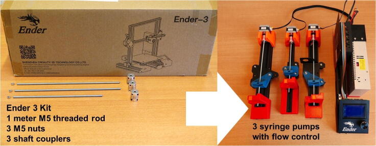
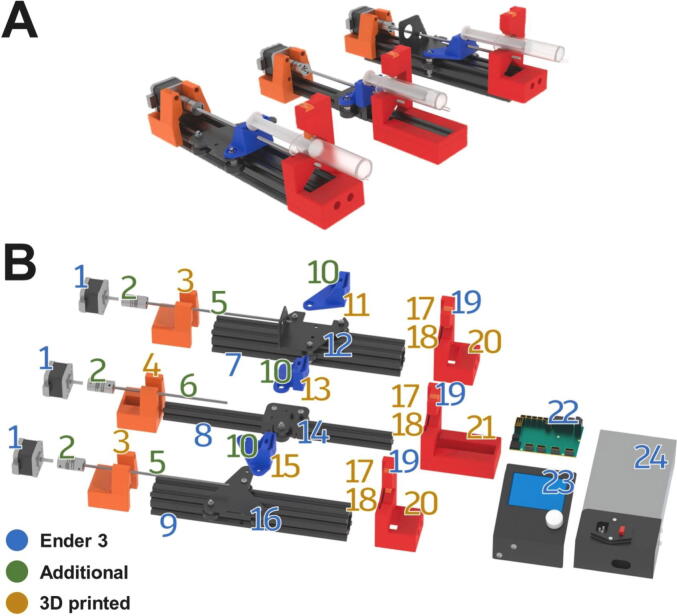
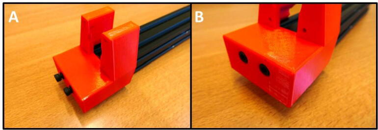
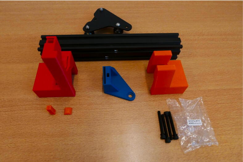
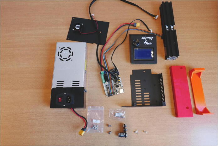
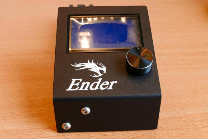
A cheap, open source 3D printer (Creality Ender 3) is transformed into an Open Hardware, programmable syringe pump set. Only 3 parts need to be purchased outside of the printer kit. All other parts are either in the Ender 3 kit, or can be 3D printed. No prior knowledge in electronics or programming languages is required. The pumps are controlled by the 3D printer firmware and motherboard and programmed in simple G-code text files. The total cost of a three pumps setup is ∼€170. The pumps are capable of reaching stable flows down to 5 µL/min using cheap, disposable 10 mL syringes. Higher flow speeds are also achievable, in the order of mL/min.

Keywords: Flow chemistry; Microfluidics; Syringe pumps.


Conflict of interest statement

The authors declare that they have no known competing financial interests or personal relationships that could have appeared to influence the work reported in this paper.

Figures

None
Graphical abstract
Fig. 1
Fig. 1
An Ender 3 3D printer kit can be repurposed to build a three channel syringe pump system. Additional purchased components are limited to one meter M5 threaded rod, three M5 nuts and three 5 × 5 shaft couplers. All custom parts can be 3D printed.
Fig. 2
Fig. 2
A) Render of the three pump channels. B) Exploded view of pump parts with number indication the parts (Table 3). Blue numbers: Parts included in the Ender 3 kit. Green numbers: Additional purchased parts. Yellow numbers: 3D printed designs. (For interpretation of the references to colour in this figure legend, the reader is referred to the web version of this article.)
Fig. 3
Fig. 3
A) All parts included in the Ender 3 kit. B) All parts used in the syringe pump system.
Fig. 4
Fig. 4
Necessary parts to build the Extruder Plate Pump Channel frame: Extruder head, M4 × 16 screws, 20 × 20 rail, E End Mount, E Slide Mount, E Stepper Mount, Clamp Bar and Dovetail Cap.
Fig. 5
Fig. 5
Preparing the E Plate for use in the pump. A) Extruder head overview. B) Removal of hotend shroud screws. These screws need to be saved for later use. C) Removal of the hotend. D) Loosening two screws in preparation for the Slider Mount.
Fig. 6
Fig. 6
Mounting the E Slide Mount. A) E Slide mount fitted to the E Plate. B) Eccentric adjuster for the guidance mechanism.
Fig. 7
Fig. 7
E Stepper Mount installation procedure. A) E Stepper Mount and 20 × 20 rail. B) Rail slides into E Stepper Mount. C) E Stepper Mount secured with M4 × 16 screws.
Fig. 8
Fig. 8
Tension adjustment of the E Slide Mount rollers.
Fig. 9
Fig. 9
A) E End Mount next to 20 × 20 rail. B) E End Mount fastened using 2 M4 × 16 screws.
Fig. 10
Fig. 10
Preparing the stepper motor for installation. A) Overview of the E Plate pump and stepper. B) Removal of bracket. C) Removal of shaft coupler. D) Stepper ready for use in pump.
Fig. 11
Fig. 11
Stepper motor mounting. A) Gathering M3 × 6 screws from the Y stepper. B) All parts to be combined. C) Stepper motor mounted on the E Stepper Mount.
Fig. 12
Fig. 12
M5 Threaded rods cut to length. Two 27 cm rods for the X Plate and X Motor Plate pumps, 22 cm rod for the E Plate pump.
Fig. 13
Fig. 13
Installation of the threaded rod and shaft coupler. A) All components laid out. B) Shaft coupler installation. C) Fixing the threaded rod to the E Slide Mount using an M5 nut. D) Threaded rod clamped in the shaft coupler.
Fig. 14
Fig. 14
Obtaining the springs for the syringe clamp mechanism. A) Remove the spring clips holding the printbed cover. B) Remove the plastic handwheel. C) Remove the machine screw. D) The spring can now be removed and used in the pump.
Fig. 15
Fig. 15
Fitting the syringe clamping mechanism. A) The necessary parts: Spring, Clamp Bar and Dovetail Cap. B) Clamp Bar installed in the slot. C) Spring placed on top of the Clamp Bar. D) The slot closed off with a Dovetail Cap, securing the mechanism in place.
Fig. 16
Fig. 16
Gathering the 40 × 40 rail. A) The rail still mounted to the Ender 3 base. B) Loosen the M5 × 45 screws to remove the rail. C) Using a hex wrench, the end cap can be pushed out.
Fig. 17
Fig. 17
Gathering the second 40 × 40 rail. A) Removing the M5 × 45 screws. B) Removing the electronics case.
Fig. 18
Fig. 18
The parts needed to build the X Motor Plate pump.
Fig. 19
Fig. 19
Procedure for disassembling the X Motor Assembly. A) Peel away the sticker. B) Remove the three roller screws. C) Remove the pulley cover. D) The freed up parts. Save the stepper motor. E) Remove all screws and the spring indicated in red. F) Remove the screws holding the filament clamp in place. (For interpretation of the references to colour in this figure legend, the reader is referred to the web version of this article.)
Fig. 20
Fig. 20
M3 × 10 screws to be used for later steps in the build guide.
Fig. 21
Fig. 21
Installing the X Motor Slide Mount. A) 3D printed part mounted on the X Motor Plate. B) Fitting the assembly on the rail.
Fig. 22
Fig. 22
Stepper pulley removal process. A) Overview of the tool, parts and stepper. B) Fitting the M5 nut in the tool. C) Removing the pulley with the tool. D) Stepper motor ready for use in the pump.
Fig. 23
Fig. 23
Installing the X X Motor End Mount. A) Fitting the mount on the rail. B) Fully installed.
Fig. 24
Fig. 24
The installed X X Motor End Mount.
Fig. 25
Fig. 25
The stepper motor will be mounted with M3 × 10 screws. A) Take the M3 × 10 screws from the fan mounted on the extruder head. B) Ready to install the stepper motor.
Fig. 26
Fig. 26
Installed threaded rod in the X Motor Plate pump.
Fig. 27
Fig. 27
Installed syringe clamp mechanism.
Fig. 28
Fig. 28
All the parts needed to build the X Plate Pump frame.
Fig. 29
Fig. 29
Building the X Plate Pump frame. A) X X Motor Stepper Mount installation. B) X Slide Mount orientation. C) Rail assembly D) Fastening the M5 × 45 screws on the X X Motor End Mount. E) Completed X Plate Pump frame.
Fig. 30
Fig. 30
Stepper motor installed in the X Plate Pump frame.
Fig. 31
Fig. 31
Threaded rod installed in the X Plate Pump.
Fig. 32
Fig. 32
The completed X Plate Pump.
Fig. 33
Fig. 33
Removing the Electronics Box from the Ender 3 base. A) Overview of the underside of the base. B) Y limit switch connector. C) M5 × 45 screws, holding the base to the buildplate. D) One of the two mounting screws. E) Second mounting screw. F) The detached Electronics box.
Fig. 34
Fig. 34
Freeing up the cable assembly to remove redundant cabling. A) Opening the Electronics Box. B) Removing the board mounting screws. Yellow circle indicates the removed fan connector. C) Cutting the zip tie. D) Removing the tape at the braid ends. (For interpretation of the references to colour in this figure legend, the reader is referred to the web version of this article.)
Fig. 35
Fig. 35
Removal of redundant cables. A) All cables to remove are indicated in red. B) After cable removal. C) Remove the Z stepper cable (red) and replace with the E stepper cable (yellow). (For interpretation of the references to colour in this figure legend, the reader is referred to the web version of this article.)
Fig. 36
Fig. 36
Overview of parts for the Control Unit.
Fig. 37
Fig. 37
LCD mounted on the 40 × 40 rail.
Fig. 38
Fig. 38
Installing the PSU on the 40 × 40 rail. A) Reuse the M4 screws and T nuts from the X Belt Tensioner. B) Insert T nuts into the rail and screws into the PSU mount. Tighten the screws. C) Screw the PSU to the PSU mount using the M4 × 20 screws. D) PSU mounted to the 40 × 40 rail.
Fig. 39
Fig. 39
Rebuilding the Electronics Box. A) Electronics Board back in place, fan reattached. B) Cover replaced.
Fig. 40
Fig. 40
Attaching the Electronics Box to the Control Unit. A) Attach the Electronics Box and Electronics Base. B) Connect to the PSU. C) Attach the rainbow colored cable to the LCD.
Fig. 41
Fig. 41
The fully assembled pump system, with the stepper motor cables attached.

References

    1. Zeng W., Jacobi I., Beck D.J., Li S., Stone H.A. Characterization of syringe-pump-driven induced pressure fluctuations in elastic microchannels. Lab. Chip. 2015;15(4):1110–1115. doi: 10.1039/C4LC01347F. - DOI - PubMed
    1. Zhao F., Cambié D., Hessel V., Debije M.G., Noël T. Real-time reaction control for solar production of chemicals under fluctuating irradiance. Green Chem. 2018;20(11):2459–2464. doi: 10.1039/C8GC00613J. - DOI
    1. Convery N., Gadegaard N. 30 years of microfluidics. Micro Nano Eng. 2019;2:76–91. doi: 10.1016/j.mne.2019.01.003. - DOI
    1. Pearce J.M., Anzalone N.C., Heldt C.L. Open-source wax RepRap 3-D printer for rapid prototyping paper-based microfluidics. J. Lab. Autom. 2016;21(4):510–516. doi: 10.1177/2211068215624408. - DOI - PubMed
    1. Khnouf R., Karasneh D., Abdulhay E., Abdelhay A., Sheng W., Fan Z.H. Microfluidics-based device for the measurement of blood viscosity and its modeling based on shear rate, temperature, and heparin concentration. Biomed. Microdevices. 2019;21:80. doi: 10.1007/s10544-019-0426-5. - DOI - PubMed

LinkOut - more resources