. 2022 May 25;12(1):8895.
doi: 10.1038/s41598-022-12860-8.

A portable non-invasive microwave based head imaging system using compact metamaterial loaded 3D unidirectional antenna for stroke detection

Affiliations

A portable non-invasive microwave based head imaging system using compact metamaterial loaded 3D unidirectional antenna for stroke detection

Mohammad Shahidul Islam et al. Sci Rep. .

Abstract

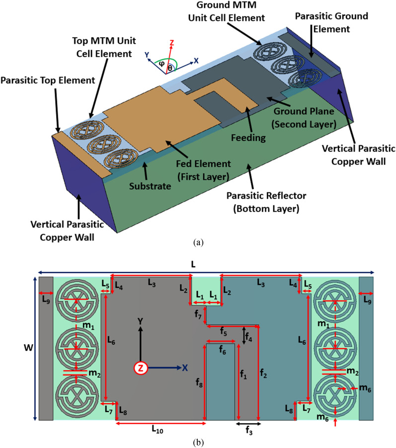
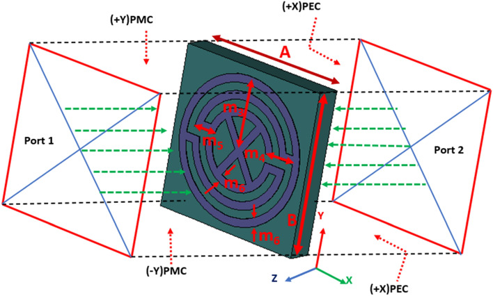
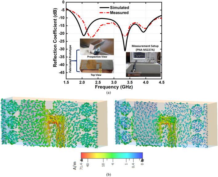
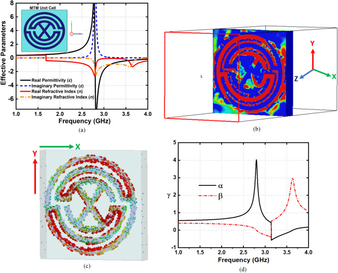
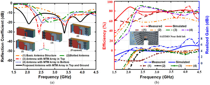
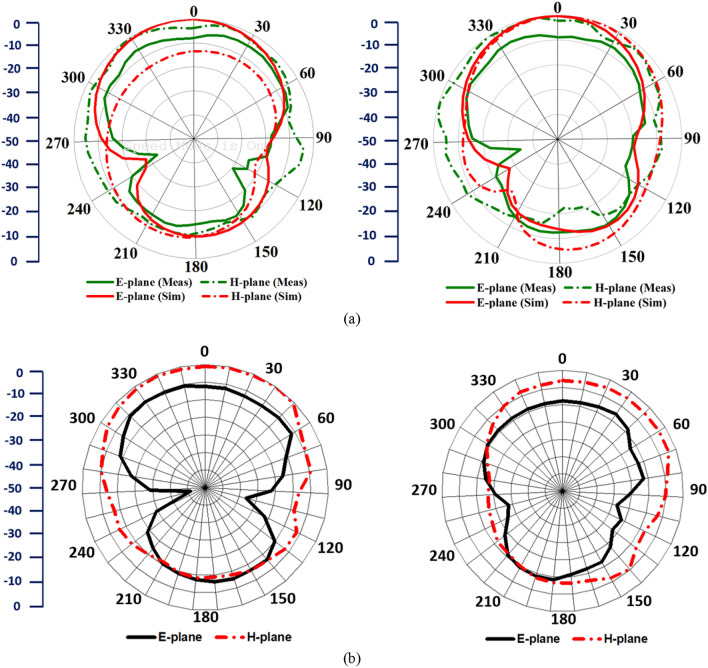
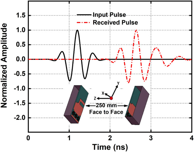
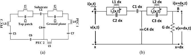
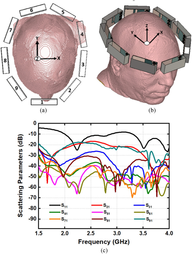
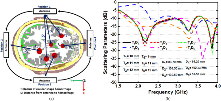
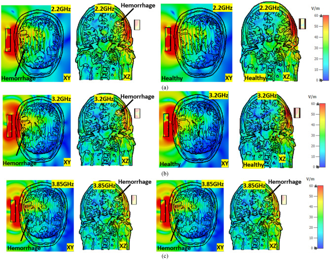
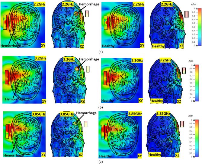
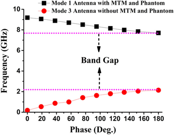
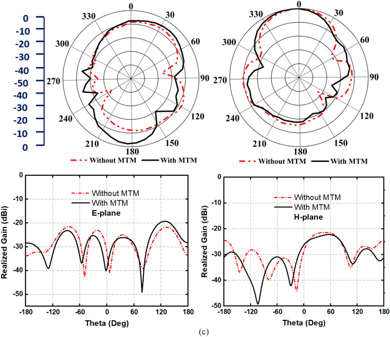
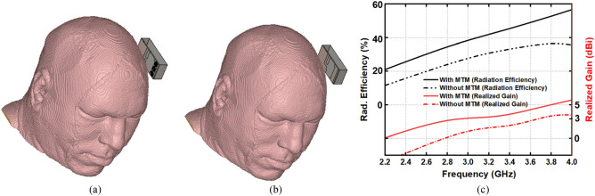
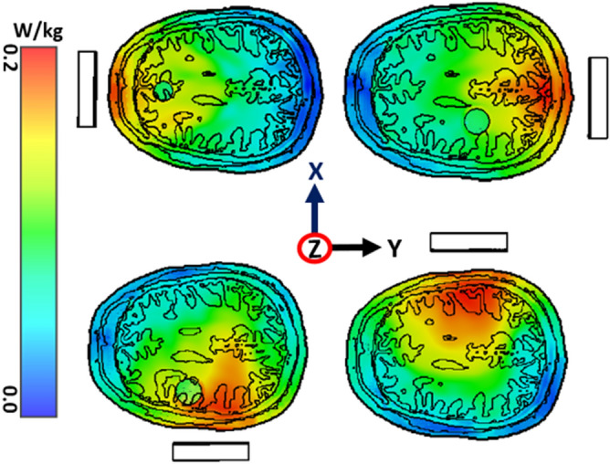
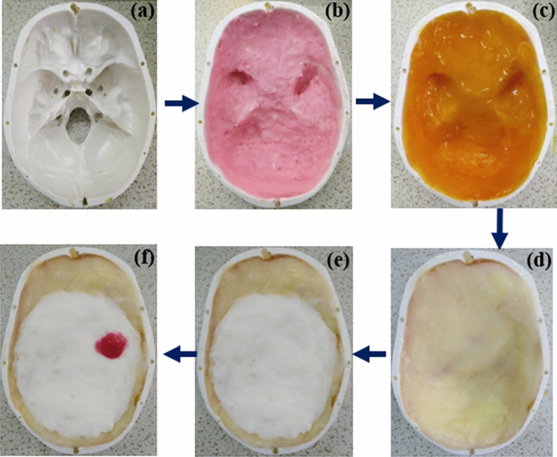
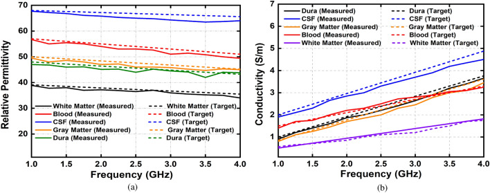
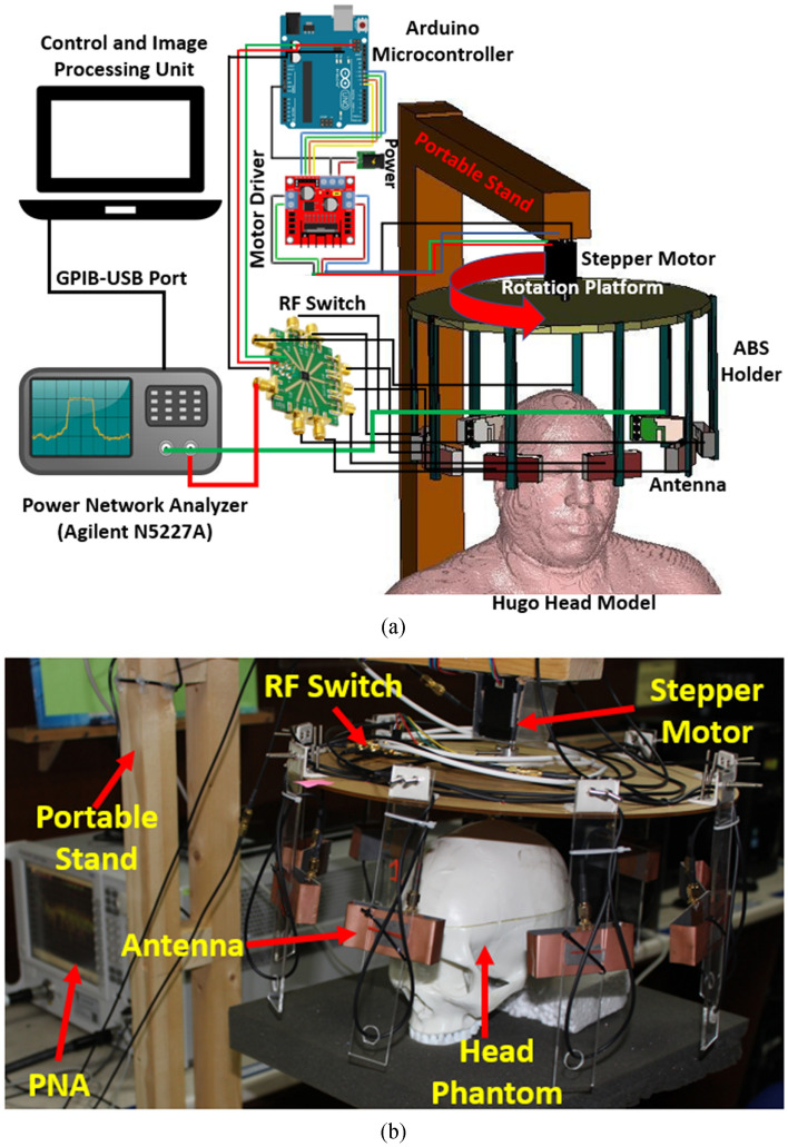
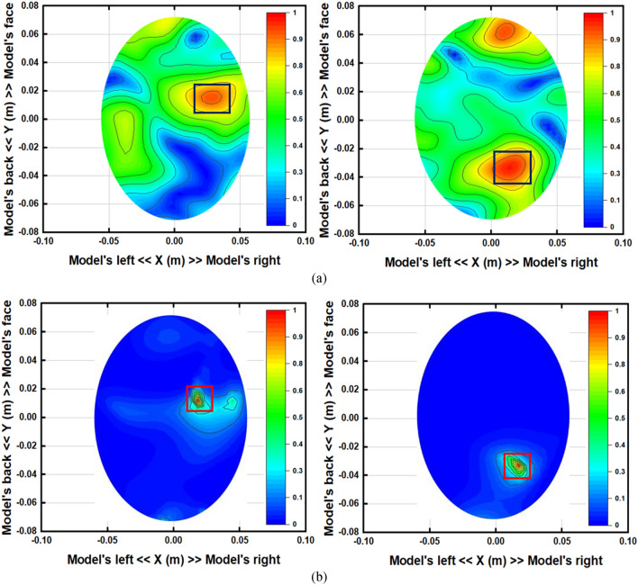
A metamaterial (MTM) loaded compact three-dimensional antenna is presented for the portable, low-cost, non-invasive microwave head imaging system. The antenna has two slotted dipole elements with finite arrays of MTM unit cell and a folded parasitic patch that attains directional radiation patterns with 80% of fractional bandwidth. The operating frequency of the antenna is 1.95-4.5 GHz. The optimization of MTM unit cell is performed to increase the operational bandwidth, realized gain, and efficiency of the antenna within the frequency regime. It is also explored to improve radiation efficiency and gain when placed to head proximity. One-dimensional mathematical modelling is analyzed to precisely estimate the power distribution that validates the performance of the proposed antenna. To verify the imaging capability of the proposed system, an array of 9 antennas and a realistic three-dimensional tissue-emulating experimental semi-solid head phantom are fabricated and measured. The backscattered signal is collected from different antenna positions and processed by the updated Iterative Correction of Coherence Factor Delay-Multiply-and-Sum beamforming algorithm to reconstruct the hemorrhage images. The reconstructed images in simulation and experimental environment demonstrate the feasibility of the proposed system as a portable platform to successfully detect and locate the hemorrhages inside the brain.


Conflict of interest statement

The authors declare no competing interests.

Figures

Figure 1
Figure 1
Schematic profile of the proposed MTM-loaded 3-D antenna. (a) Perspective view. (b) Top view. Dimensions (mm): L = 70, W = 30, L1 = 3, L2 = 6, L3 = 17, L4 = 3.5, L5 = 3, L6 = 22.5, L7 = 3, L8 = 4, L9 = 3, f1 = 16, f2 = 20, f3 = 5, f4 = 4, f5 = 11, f6 = 6, f7 = 4, f8 = 16, m1 = 10, m2 = 1, m6 = 0.5.
Figure 2
Figure 2
Simulation setup of MTM unit cell structure. Dimensions (mm): A = 10, B = 10, m3 = 4.5, m4 = 2, m5 = 1.5, and m6 = 0.5.
Figure 3
Figure 3
(a) Simulated and measured reflection coefficient and (b) surface current distribution at 2.1 GHz and 3.34 GHz, respectively.
Figure 4
Figure 4
(a) Retrieved effective permittivity and refractive index of the MTM unit cell structure (b) Surface current at 2.8 GHz (c) E-field at 2.8 GHz, and (d) Propagation constant.
Figure 5
Figure 5
Evolution of the proposed MTM-loaded 3D-antenna (a) scattering parameters. (b) Efficiency and realized gain.
Figure 6
Figure 6
(a) Simulated and measured E-plane and H-plane (far-field), and (b) Measured E-plane and H-plane (near-field), at 2.2 GHz and 3.34 GHz, respectively.
Figure 7
Figure 7
Time-domain performance: Input and received pulse.
Figure 8
Figure 8
Analytical representation of 3D antenna (a) equivalent circuit of the 3D antenna (b) simplified equivalent circuit of 3D antenna for mathematical modelling.
Figure 9
Figure 9
(a) Top view (b) perspective view of nine antenna setup and (c) antenna scattering parameters with mutual coupling effect.
Figure 10
Figure 10
(a) Different antenna position with different size and location of hemorrhages and (b) scattering parameters.
Figure 11
Figure 11
E-field distribution of healthy and unhealthy head at (a) 2.2 GHz, (b) 3.2 GHz, and (c) 3.85 GHz, respectively.
Figure 12
Figure 12
H-field distribution of healthy and unhealthy head at (a) 2.2 GHz, (b) 3.2 GHz, and (c) 3.85 GHz, respectively.
Figure 13
Figure 13
EMT perspective view for a phantom cross-section and the proposed antenna with relevant dielectric parameters.
Figure 14
Figure 14
Dispersion diagram of the proposed antenna.
Figure 15
Figure 15
Antenna radiation and cross-polarization behavior with and without metamaterial structure in close proximity to the head phantom. E-plane and H-place at (a) 2.2 GHz, (b) 3.2 GHz, and (c) 3.85 GHz, respectively.
Figure 15
Figure 15
Antenna radiation and cross-polarization behavior with and without metamaterial structure in close proximity to the head phantom. E-plane and H-place at (a) 2.2 GHz, (b) 3.2 GHz, and (c) 3.85 GHz, respectively.
Figure 16
Figure 16
Near-field head model analysis (a) with MTM (b) without MTM and (c) radiation efficiency and realized gain.
Figure 17
Figure 17
The specific absorption rate (SAR) inside the head phantom with antenna operation in different positions within XY-plane with 1mW input power at 2.20 GHz.
Figure 18
Figure 18
Steps of 3D head phantom fabrication. (a) Blank (b) Dura (c) CSF (d) gray matter (e) white matter (f) phantom with hemorrhage.
Figure 19
Figure 19
Measurement procedures of the fabricated head phantom.
Figure 20
Figure 20
Actual and measured values of human head phantom (a) relative permittivity and (b) conductivity.
Figure 21
Figure 21
Sample (a) scattering parameters and (b) phase (antenna 2: transmitter).
Figure 22
Figure 22
Simulated near-field image reconstruction (a) Perspective head model with single and double hemorrhage (b) single hemorrhage detection with and without MTM loaded antenna (c) double hemorrhage detection with and without MTM loaded antenna.
Figure 23
Figure 23
The proposed portable head imaging system (a) simulation model, and (b) perspective view with human head phantom.
Figure 24
Figure 24
The reconstructed images using the proposed antenna in two different positions. (a) Applying conventional DMAS and (b) applying IC-CF-DMAS. The small red square marks the inserted hemorrhage.

References

    1. Frykberg RG, Lavery LA, Pham H, Harvey C, Harkless L, Veves A. Role of neuropathy and high foot pressures in diabetic foot ulceration. Diabetes Care. 1998;21:1714. doi: 10.2337/diacare.21.10.1714. - DOI - PubMed
    1. Fernando ME, Crowther RG, Lazzarini PA, Sangla KS, Buttner P, Golledge J. Gait parameters of people with diabetes-related neuropathic plantar foot ulcers. Clin Biomech. 2016;37:98–107. doi: 10.1016/j.clinbiomech.2016.06.006. - DOI - PubMed
    1. Boulton, A. The diabetic foot: from art to science. The 18th Camillo Golgi lecture. Diabetologia, 47(8):1343–1353 (2004). - PubMed
    1. Farahpour N, et al. Gait ground reaction force characteristics of low back pain patients with pronated foot and able-bodied individuals with and without foot pronation. J. Biomech. 2016;49(9):1705–1710. doi: 10.1016/j.jbiomech.2016.03.056. - DOI - PubMed
    1. Sacco IC, et al. Alterations in the lower limb joint moments precede the peripheral neuropathy diagnosis in diabetes patients. Diabetes Technol. Ther. 2015;17(6):405–412. doi: 10.1089/dia.2014.0284. - DOI - PubMed

Publication types