. 2022 May 27;376(6596):1006-1012.
doi: 10.1126/science.abm1703. Epub 2022 May 26.

A transient, closed-loop network of wireless, body-integrated devices for autonomous electrotherapy

Affiliations

A transient, closed-loop network of wireless, body-integrated devices for autonomous electrotherapy

Yeon Sik Choi et al. Science. .

Abstract

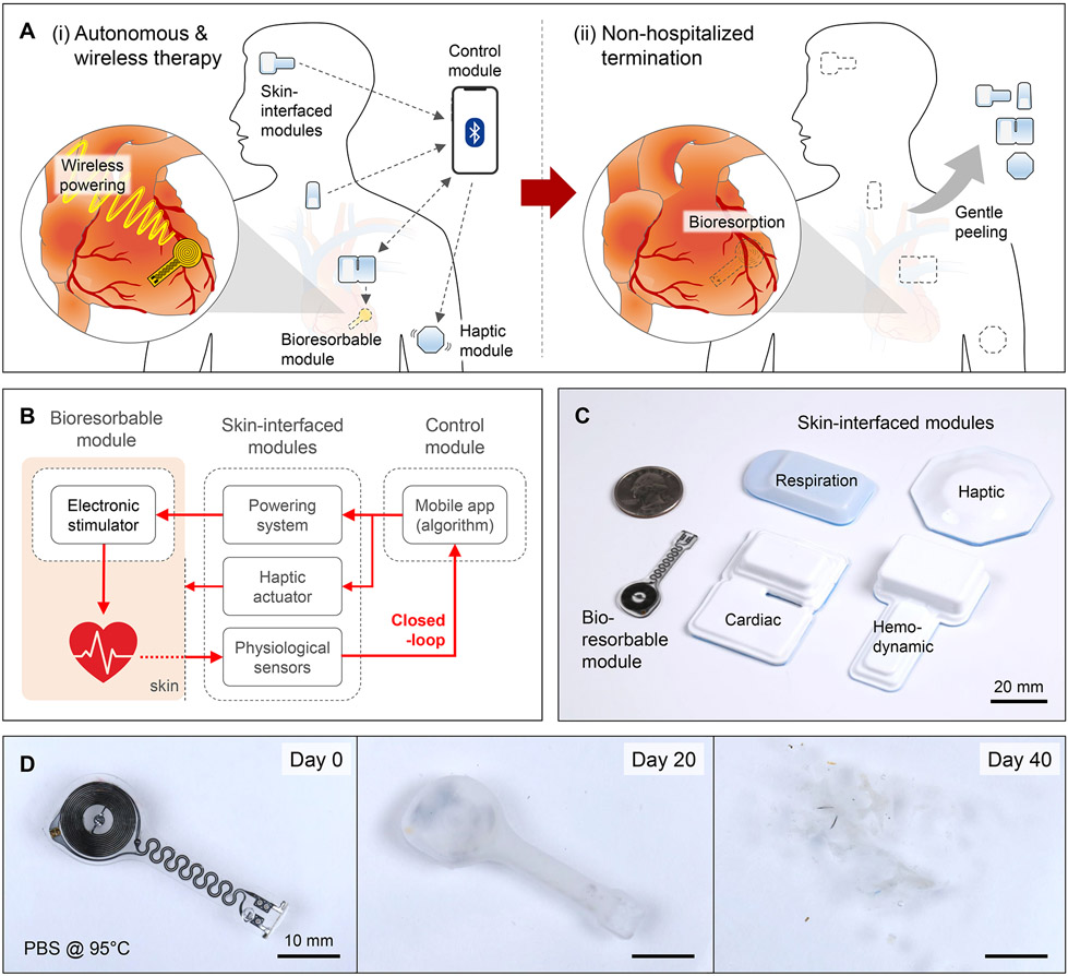
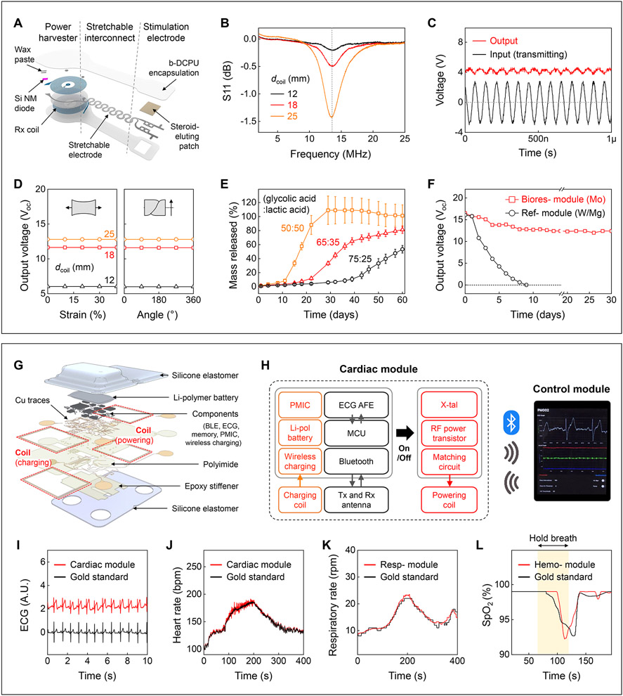
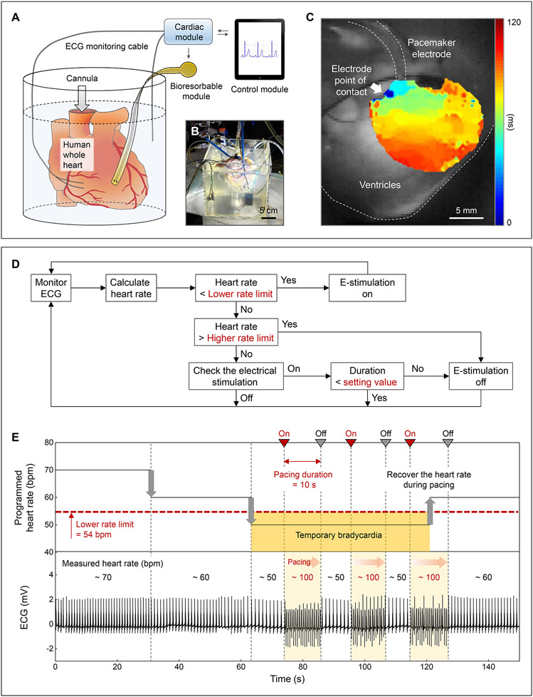
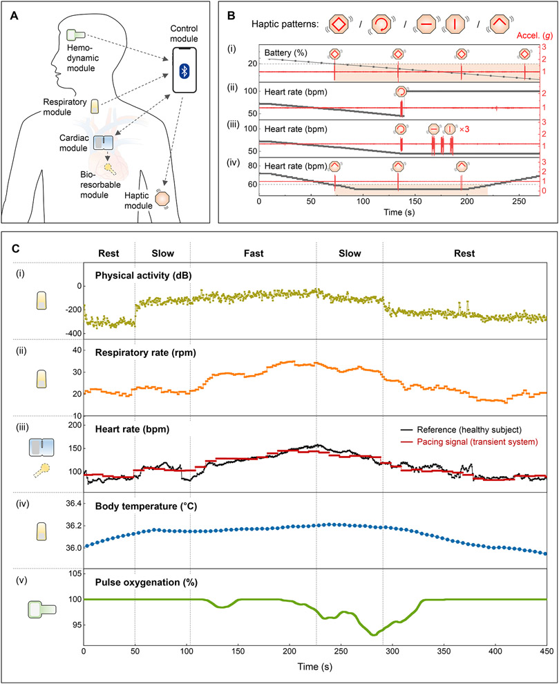
Temporary postoperative cardiac pacing requires devices with percutaneous leads and external wired power and control systems. This hardware introduces risks for infection, limitations on patient mobility, and requirements for surgical extraction procedures. Bioresorbable pacemakers mitigate some of these disadvantages, but they demand pairing with external, wired systems and secondary mechanisms for control. We present a transient closed-loop system that combines a time-synchronized, wireless network of skin-integrated devices with an advanced bioresorbable pacemaker to control cardiac rhythms, track cardiopulmonary status, provide multihaptic feedback, and enable transient operation with minimal patient burden. The result provides a range of autonomous, rate-adaptive cardiac pacing capabilities, as demonstrated in rat, canine, and human heart studies. This work establishes an engineering framework for closed-loop temporary electrotherapy using wirelessly linked, body-integrated bioelectronic devices.


Conflict of interest statement

Competing interests: IRE consults for Cardialen, Sana Biotechnology, Zoll, and AliveCor.

Figures

Fig. 1.
Fig. 1.. Transient closed-loop system for temporary cardiac pacing.
(A) Schematic illustration of a system for (i) autonomous and wireless pacing therapy and (ii) non-hospitalized termination. (B) Operational diagram for continuous monitoring, autonomous treatment, and haptic feedback. (C) Photographs showing the sizes of the various modules, relative to a U.S. quarter. (D) Photographs of a bioresorbable module at different time points during immersion in a simulated biofluid (PBS; 95 °C).
Fig. 2.
Fig. 2.. Materials, design features.
(A) Schematic illustration of a bioresorbable module. (B) S11 values of the Rx coils with different diameters (dcoil). (C) Example output waveform (red; dcoil = 12 mm) wirelessly generated by an alternating current (black; ~3 Vpp; 13.56 MHz) applied to the Tx coil. (D) Output voltage of devices as a function of tensile strain (left) and twist angle (right) at a fixed transmitting voltage (4 Vpp) and frequency (13.56 MHz). (E) Drug release behaviors of steroid eluting patches with three different ratios of base polymer. (F) Measurements of output voltages of a bioresorbable module (red square, 10 μm thick Mo) and a reference module (black circle, W/Mg with 700 nm / 50 μm thickness) immersed in PBS (37 °C). (G) Schematic illustration of a skin-interfaced cardiac module. (H) System block diagram of the cardiac module. PMIC, power management integrated circuit. (I-L) Comparisons of ECG, HR, respiratory rate, and SpO2 level determined by the skin-interfaced modules (red; I, J, cardiac; K, respiratory; L, hemodynamic) and a reference device (black). In L, healthy subject holds breath for 60 s (yellow background).
Fig. 3.
Fig. 3.. Treatment of temporary bradycardia.
(A) Schematic illustration and (B) photograph of a Langendorff-perfused human whole heart model with a transient closed-loop system (dcoil = 25 mm). (C) Action potential maps obtained by optical mapping of the human epicardium. (D) Flow chart of closed-loop hysteresis pacing to activate the pacemaker upon automatic detection of bradycardia (Supplementary Text 8). (E) Programmed HR (top) and measured ECG (bottom) of a human whole heart. Set parameters: lower rate limit, 54 bpm; pacing duration, 10 s; pacing rate, 100 bpm.
Fig. 4.
Fig. 4.. Patient feedback and adaptive pacing functions.
(A) Schematic illustration of a transient closed-loop system. (B) Demonstration of the patient awareness function using a multi-haptic module. Accelerometer data (z-axis) corresponds to vibrations of the haptic actuators. (C) Results of clinical tests with a healthy human subject. (i) Calculated physical activity and (ii) respiratory rate using data from the respiratory module. (iii) Comparison of the heart rate (black) of a healthy human subject monitored by the cardiac module and rate-adaptive pacing signals (red) processed from the algorithm. (iv) Calibrated and measured changes in core body temperatures using data from the respiratory module. (v) Representative SpO2 measurements from the hemodynamic module.

Comment in

References

    1. Kaszala K, Ellenbogen KA, Circulation. 122, 1328–1340 (2010). - PubMed
    1. Hovorka R, Diabet. Med 23, 1–12 (2006). - PubMed
    1. Mickle AD et al., Nature. 565, 361–365 (2019). - PMC - PubMed
    1. Austin JL, Preis LK, Crampton RS, Beller GA, Martin RP, Am. J. Cardiol 49, 301–306 (1982). - PubMed
    1. Lumia FJ, Rios JC, Chest. 64, 604–608 (1973). - PubMed