

Design of a Deployable Helix Antenna at L-Band for a 1-Unit CubeSat: From Theoretical Analysis to Flight Model Results
- PMID: 35632038
- PMCID: PMC9144964
- DOI: 10.3390/s22103633
Design of a Deployable Helix Antenna at L-Band for a 1-Unit CubeSat: From Theoretical Analysis to Flight Model Results
Abstract
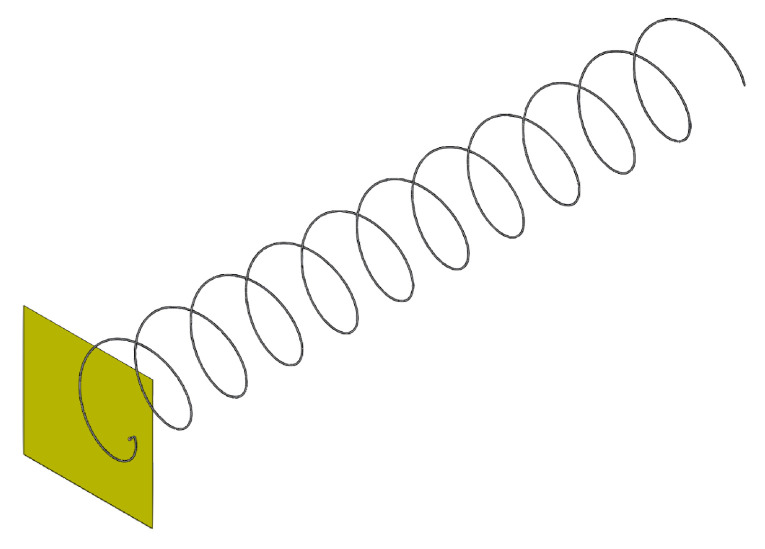
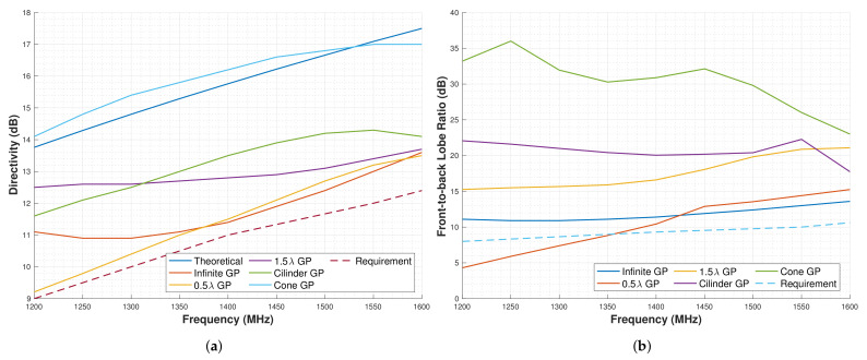
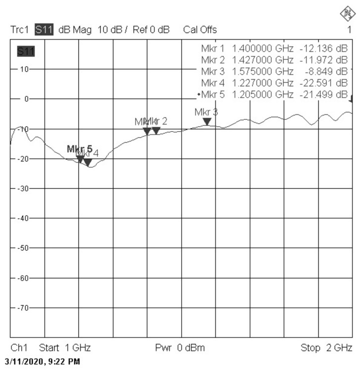
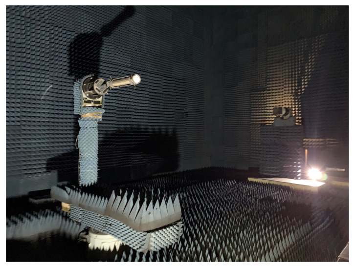
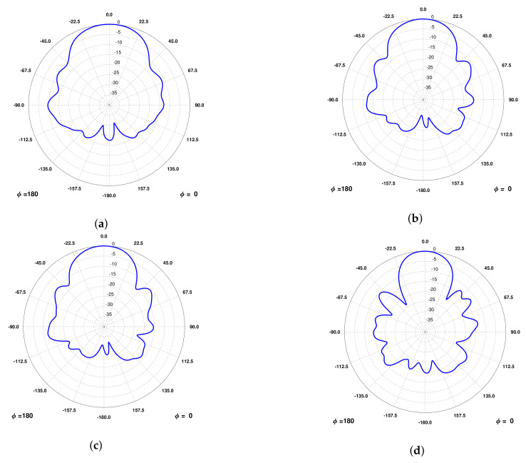
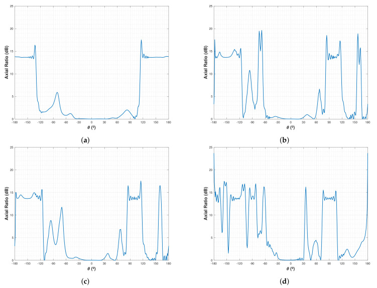
The 3Cat-4 mission aims at demonstrating the capabilities of a CubeSat to perform Earth Observation (EO) by integrating a combined GNSS-R and Microwave Radiometer payload into a 1-Unit CubeSat. One of the greatest challenges is the design of an antenna that respects the 1-Unit CubeSat envelope while operating at the different frequency bands: Global Positioning System (GPS) L1 and Galileo E1 band (1575 MHz), GPS L2 band (1227 MHz), and the microwave radiometry band (1400-1427 MHz). Moreover, it requires between 8 and 12 dB of directivity depending on the band whilst providing at least 10 dB of front-to-back lobe ratio in L1 and L2 GPS bands. After a trade-off analysis on the type of antenna that could be used, a helix antenna was found to be the most suitable option to comply with the requirements, since it can be stowed during launch and deployed once in orbit. This article presents the antenna design from a radiation performance point of view starting with a theoretical analysis, then presenting the numerical simulations, the measurements in an Engineering Model (EM), and finally the final design and performance of the Flight Model (FM).
Keywords: CubeSat; Earth Observation; L-Band; antenna; deployable; helix; nanosatellite.
Conflict of interest statement
The funders had no role in the design of the study; in the collection, analyses, or interpretation of data; in the writing of the manuscript, or in the decision to publish the results.
Figures
References
-
- Nasa Scienc TIROS. [(accessed on 30 March 2022)]; Available online: https://science.nasa.gov/missions/tiros.
-
- ESA Earth Online Envisat Mission Summary. [(accessed on 30 March 2022)]. Available online: https://earth.esa.int/web/guest/missions/esa-eo-missions/envisat/mission....
-
- NASA UARS Science Accomplishments. [(accessed on 30 March 2022)]; Available online: https://www.nasa.gov/mission_pages/uars/uars_science.html.
-
- ESA Sentinel. [(accessed on 30 March 2022)]. Available online: https://sentinels.copernicus.eu/web/sentinel/home.
-
- CubeSat Origin of the New Space Evolution. [(accessed on 30 March 2022)]. Available online: http://www.cubesat.org/
Grants and funding
- RTI2018-099008-B-C21/AEI/10.13039/501100011033/Ministry of Economy, Industry and Competitiveness
- 2017 SGR 376/Secretaria d'Universitats i Recerca del Departament d'Empresa i Coneixement de la Generalitat de Catalunya
- 2017 SGR 219/Secretaria d'Universitats i Recerca del Departament d'Empresa i Coneixement de la Generalitat de Catalunya
- 10.13039/501100011033/MCIN / AEI
- FI-2019/Agency for Administration of University and Research
LinkOut - more resources
Full Text Sources
Miscellaneous
