. 2022 Jun 3;17(6):e0269497.
doi: 10.1371/journal.pone.0269497. eCollection 2022.

A semantics, energy-based approach to automate biomodel composition

Affiliations

A semantics, energy-based approach to automate biomodel composition

Niloofar Shahidi et al. PLoS One. .

Abstract

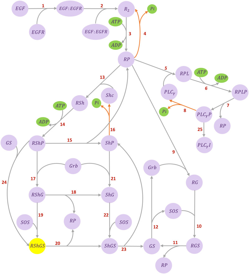
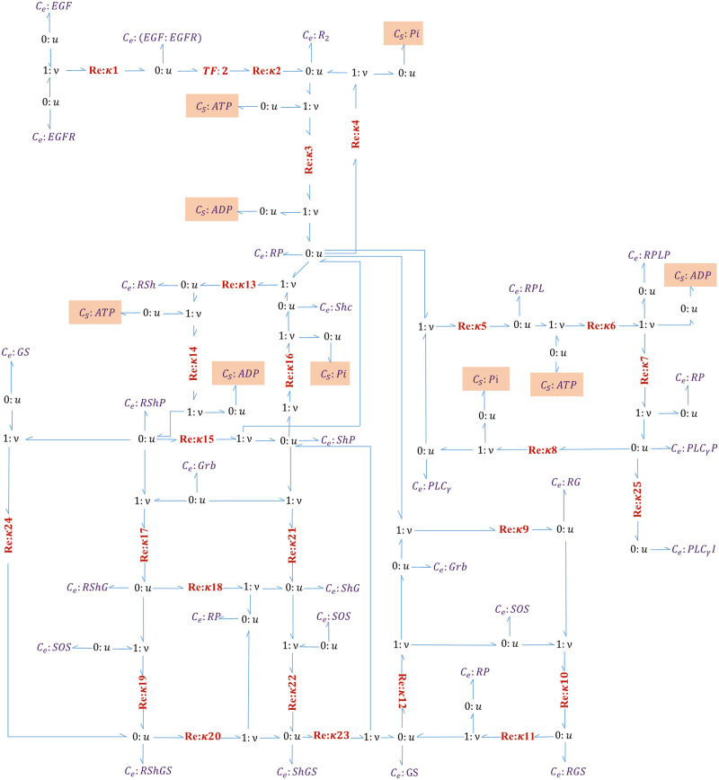
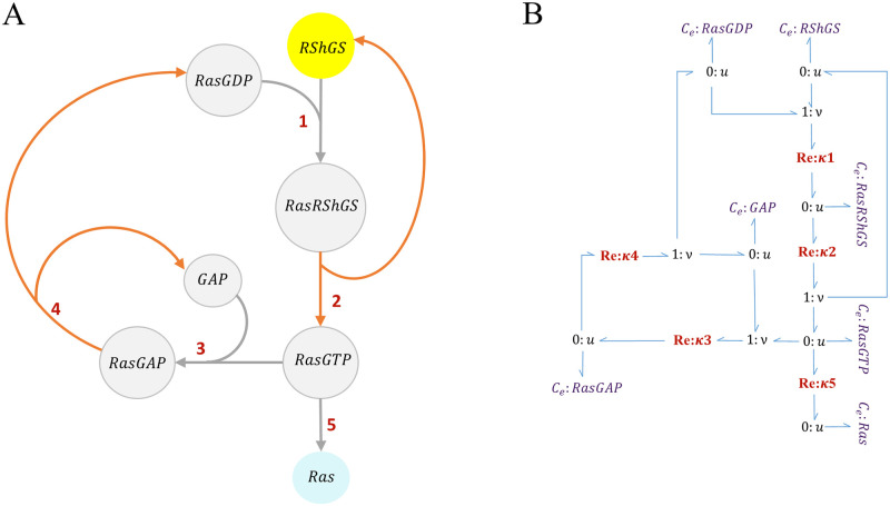
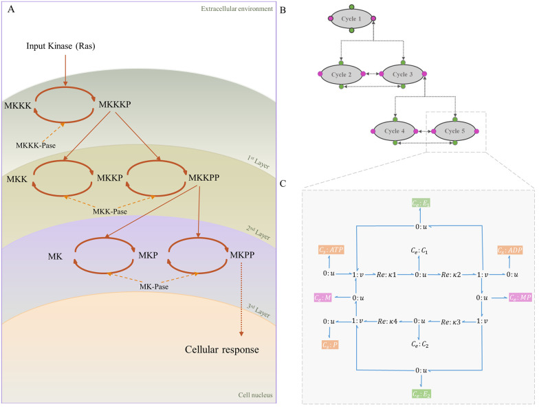
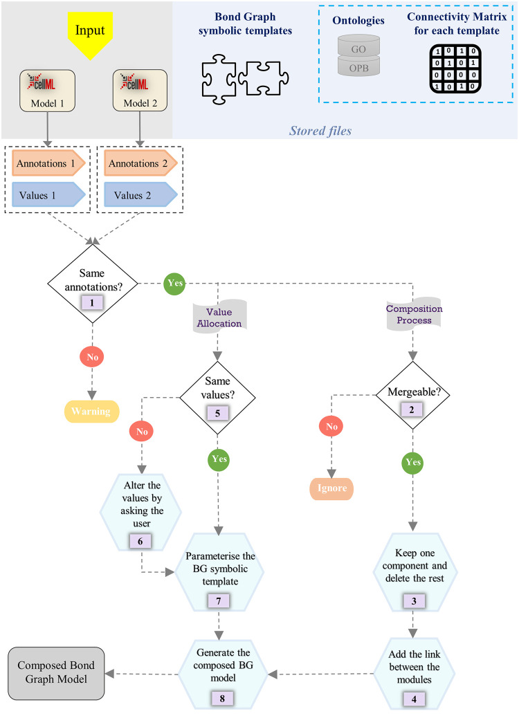
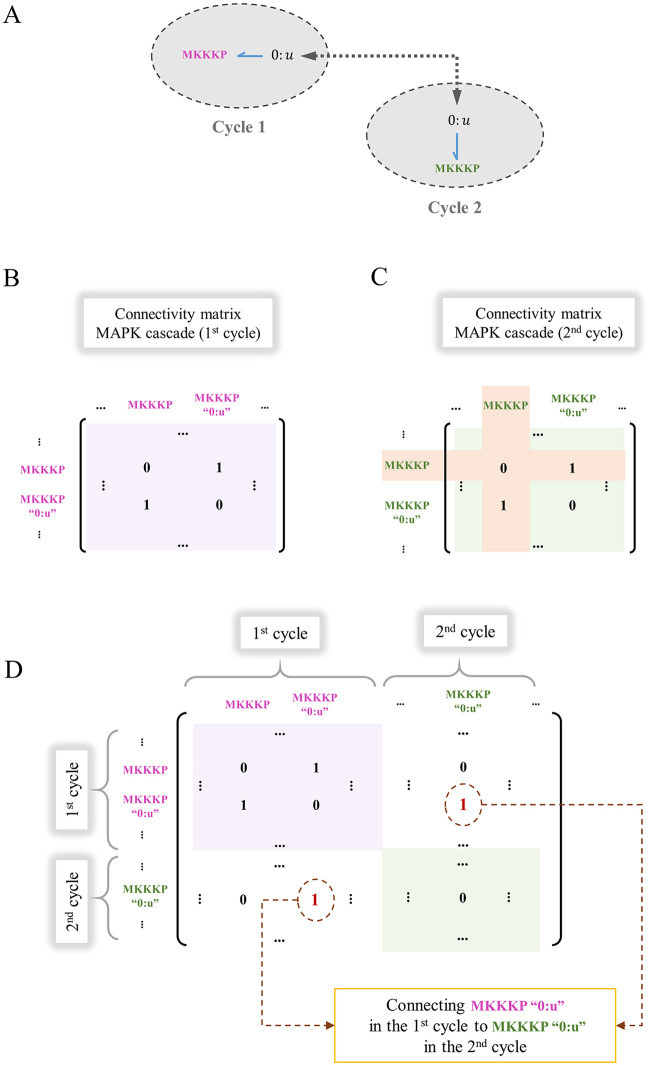
Hierarchical modelling is essential to achieving complex, large-scale models. However, not all modelling schemes support hierarchical composition, and correctly mapping points of connection between models requires comprehensive knowledge of each model's components and assumptions. To address these challenges in integrating biosimulation models, we propose an approach to automatically and confidently compose biosimulation models. The approach uses bond graphs to combine aspects of physical and thermodynamics-based modelling with biological semantics. We improved on existing approaches by using semantic annotations to automate the recognition of common components. The approach is illustrated by coupling a model of the Ras-MAPK cascade to a model of the upstream activation of EGFR. Through this methodology, we aim to assist researchers and modellers in readily having access to more comprehensive biological systems models.


Conflict of interest statement

The authors have declared that no competing interests exist.

Figures

Fig 1
Fig 1. A chemical reaction and its bond graph equivalent.
A chemical reaction with two reactants and two products. (A) Schematic of a chemical reaction where κ is the reaction rate constant, A & B are the reactants, C & D are the products, and α & β are stoichiometries; (B) Bond graph equivalent of the reaction where Ce components correspond to the species, Re corresponds to the reaction, and TF components represent the stoichiometries. Since the consumption/production rate of all the contributing species in a reaction is equal to the reaction flow rate, they share a common flow with the Re component through a ‘1: v’ junction.
Fig 2
Fig 2. An example of composing two reactions in bond graphs.
Reactions 1 and 2 represent two separate reactions in which the species C is common. To compose the reactions, the common species (C) is merged and the conservation equation at its corresponding ‘0: u’ junction alters to account for the imposed changes in structure. The conservation equation at the ‘0: u’ junction connected to the species C is vc = v1 in Reaction 1 and in Reaction 2 is vC = −v2 and in the composed reaction it changes to vC = v1v2.
Fig 3
Fig 3. Kinetic structure of the EGFR pathway.
The ATP hydrolysis species are shown in green (involved in phosphorylation and dephosphorylation reactions). The RShGS complex in yellow is mutual between the EGFR pathway and the Ras activation models. The reactions are numbered as the equations in the CellML source code. Steps 4, 8, 16 in orange represent the irreversible reactions. The network was adapted from [30].
Fig 4
Fig 4. Bond graph representation of the EGFR pathway model.
Re components are numbered according to the steps in [30]. Each Ce or CS component is connected to a ‘0: u’ junction. Where a species participates in more than one reaction, new bonds are applied to its corresponding ‘0: u’ junction to share a common chemical potential (See R-PL where it is produced in reaction 5 and consumed in reaction 6). The chemostats in orange boxes are added to the reconstructed bond graph version.
Fig 5
Fig 5. The structure of the Ras activation module.
(A) Kinetic representation. The RShGS complex in yellow is mutual between the EGFR pathway and the Ras activation modules and Ras protein in blue is mutual between the Ras activation module and the MAPK cascade module. Steps 2, 4 in orange represent the irreversible reactions. The network was adapted from [31]; (B) The bond graph representation of the Ras activation module.
Fig 6
Fig 6. The structure of the MAPK cascade.
(A) Kinetic representation. The stimulus from the extracellular environment is received (Ras) and transmitted through the MAPK cascade to the cell nucleus. The layers demonstrate the cycles with the same kinase and phosphatase enzymes; (B) MAPK cascade with five modules. Linking species are shown in colours where green corresponds to the linking enzymes and pink corresponds to unphosphorylated/phosphorylated mitogen proteins. Arrows show the links between the modules; (C) The symbolic bond graph model of each cycle. Sources of potential with fixed concentrations (Cs:ATP, Cs:ADP, and Cs:Pi) are shown in orange. (Same sources of potential within the modules are omitted in (A) and (B) for clarity).
Fig 7
Fig 7. The generic flowchart of our automated model composition approach.
The Stored files section shows the saved files for the current model composition framework. Ontologies and connectivity matrices in the blue dashed box are optional in the generic approach but were used in the current framework. The Input section shows two arbitrary CellML models to be merged using our framework but can be extended to any number of models. The main steps of the framework are denoted by numbers (1–8).
Fig 8
Fig 8. Construction of the whole-system connectivity matrix for a composed model.
The procedure is illustrated by integrating two connectivity matrices (1st and 2nd cycles in the MAPK cascade). Initially, the two cycles had identical connectivity matrices. (A) MKKKP is a common component between the first and second cycle; (B) The connectivity matrix for the 1st cycle; (C) The modified connectivity matrix for the 2nd cycle where the row and column for the common component (MKKKP) will be removed; (D) The placement of the connectivity matrices for each module on the diagonal of the whole-system connectivity matrix. The pink and green boxes indicate the connectivity matrices for the 1st and 2nd cycles, respectively. The corresponding ‘0:u’ junctions for MKKKP in the two cycles are connected by inserting two 1s (in red) to represent a bond between them (bidirectional connections between the components require the matrix be symmetric).
Fig 9
Fig 9. Bond graph schematic of adding negative feedback in the composed EGFR-Ras-MAPK bond graph model.
The negative feedback loop (red bonds) initiates from MKPP and has an enzymatic role in the first layer’s dephosphorylation reaction.
Fig 10
Fig 10. The composed modular bond graph model of EGFR-Ras-MAPK signalling pathway.
The blue dashed boxes represent the bond graph modules, the yellow boxes show the merged common components between the modules (each sharing a common potential by a ‘0: u’ junction), and the blue harpoons represent the bonds between the modules and common components. The inter-module bonds, along with the internal bonds between the components in each module, are defined and automatically applied to the model using the whole connectivity matrix. The EGFR and MAPK cycles also share common potentials with CS:ATP, CS:ADP, and CS:Pi.
Fig 11
Fig 11. Comparison between the Kholodenko et al. EGFR model and its bond graph approximation.
The simulations are given for four exemplar species in the pathway. NRMSE is calculated for each comparison in percentage. The initial concentration of EGF (the initiative molecule in the EGFR module) was 680 nM.
Fig 12
Fig 12. Comparison between the reduced Brightman & Fell Ras activation model and its bond graph approximation.
The simulations are given for four species. NRMSE is calculated for each comparison in percentage. The initial amounts in this simulation were 0 except for: RasGDP = 19800, RasGTP = 200, GAP = 15000.
Fig 13
Fig 13. The steady-state responses of the activated kinases for different input amounts in the MAPK cascade model.
The input Ras concentration is expressed on a logarithmic scale and each curve is normalised to the maximum reached concentration of that species.
Fig 14
Fig 14. Verification of the responses of activated kinases to Ras in the composed EGFR-Ras-MAPK bond graph model by comparing with the predicted steady-state responses in the MAPK cascade module.
(A) Ultrasensitivity in the composed EGFR-Ras-MAPK bond graph model. The steady-state concentrations of the kinases are: MKKKP = 1.37 nM, MKKPP = 1054.37 nM, MKPP = 987.96 nM; (B) Predicted steady-state concentration of the kinases. The purple dashed line shows the concentration of Ras at t = 100 (s) in the composed EGFR-Ras-MAPK bond graph model. The predicted steady-state concentrations of MKKKP, MKKPP, and MKPP at Ras = 0.311 nM match with the ones in the composed EGFR-Ras-MAPK bond graph model.
Fig 15
Fig 15. Activation of terminal kinases with and without negative feedback in the composed EGFR-Ras-MAPK bond graph model.
(A) Without negative feedback; (B) With negative feedback.
Fig 16
Fig 16. Time course behaviour of the terminal kinases in the composed EGFR-Ras-MAPK bond graph model with negative feedback.
Fig 17
Fig 17. Effect of different levels of ATP concentration on activated kinases in the composed EGFR-Ras-MAPK bond graph model.
(A) MKPP; (B) MKKPP; (C) MKKKP; (D) Steady-state concentration of MKKKP, MKKPP, and MKPP against relative ATP concentration. MKKKP concentration is also separately shown in a box due to its relatively small amounts compared to MKKPP and MKPP (initial concentration of common species: Ras = 0, RShGS = 0).
Fig 18
Fig 18. Effect of different levels of EGF concentration on MKPP in the composed EGFR-Ras-MAPK bond graph model.
The concentration of EGF was set to 0, 0.25%, 0.5%, 1%, 2%, 3%, 5%, 10%, and 100% of its initial concentration (680 nM). The behaviour of MKPP changes by altering the initial concentration of EGF.

Similar articles

Cited by

References

    1. Carrera J, Covert MW. Why build whole-cell models? Trends in cell biology. 2015;25(12):719–722. doi: 10.1016/j.tcb.2015.09.004 - DOI - PMC - PubMed
    1. Cooling MT, Nickerson DP, Nielsen PM, Hunter PJ. Modular modelling with Physiome standards. The Journal of physiology. 2016;594(23):6817–6831. doi: 10.1113/JP272633 - DOI - PMC - PubMed
    1. Yu T, Lloyd CM, Nickerson DP, Cooling MT, Miller AK, Garny A, et al. The physiome model repository 2. Bioinformatics. 2011;27(5):743–744. doi: 10.1093/bioinformatics/btq723 - DOI - PubMed
    1. Le Novere N, Bornstein B, Broicher A, Courtot M, Donizelli M, Dharuri H, et al. BioModels Database: a free, centralized database of curated, published, quantitative kinetic models of biochemical and cellular systems. Nucleic acids research. 2006;34(suppl_1):D689–D691. doi: 10.1093/nar/gkj092 - DOI - PMC - PubMed
    1. Clerx M, Cooling MT, Cooper J, Garny A, Moyle K, Nickerson DP, et al. CellML 2.0. Journal of Integrative Bioinformatics. 2020;17(2-3). doi: 10.1515/jib-2020-0021 - DOI - PMC - PubMed

Publication types