. 2022 Jun 3;13(1):3112.
doi: 10.1038/s41467-022-30779-6.

The influence of Holliday junction sequence and dynamics on DNA crystal self-assembly

Affiliations

The influence of Holliday junction sequence and dynamics on DNA crystal self-assembly

Chad R Simmons et al. Nat Commun. .

Abstract

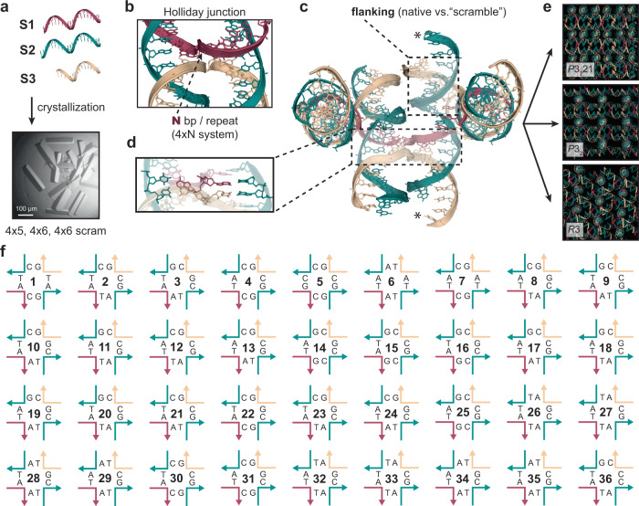
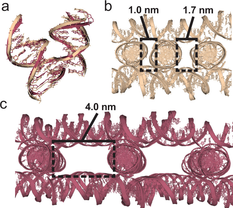
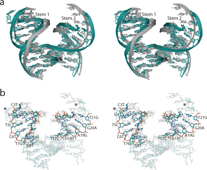
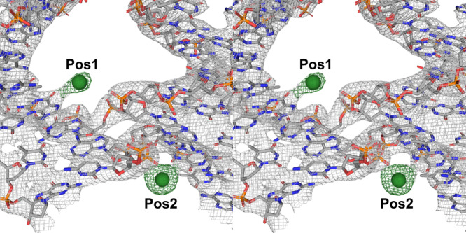
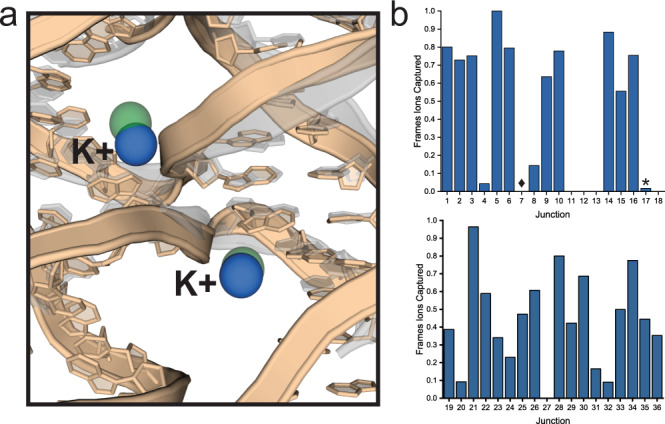
The programmable synthesis of rationally engineered crystal architectures for the precise arrangement of molecular species is a foundational goal in nanotechnology, and DNA has become one of the most prominent molecules for the construction of these materials. In particular, branched DNA junctions have been used as the central building block for the assembly of 3D lattices. Here, crystallography is used to probe the effect of all 36 immobile Holliday junction sequences on self-assembling DNA crystals. Contrary to the established paradigm in the field, most junctions yield crystals, with some enhancing the resolution or resulting in unique crystal symmetries. Unexpectedly, even the sequence adjacent to the junction has a significant effect on the crystal assemblies. Six of the immobile junction sequences are completely resistant to crystallization and thus deemed "fatal," and molecular dynamics simulations reveal that these junctions invariably lack two discrete ion binding sites that are pivotal for crystal formation. The structures and dynamics detailed here could be used to inform future designs of both crystals and DNA nanostructures more broadly, and have potential implications for the molecular engineering of applied nanoelectronics, nanophotonics, and catalysis within the crystalline context.


Conflict of interest statement

The authors declare no competing interests.

Figures

Fig. 1
Fig. 1. Schematic of the composition of the Holliday junction which is required for the self-assembly of 3D DNA lattices.
a Three oligonucleotides mediate the crystallization of two self-assembling motifs (4 × 5 and 4 × 6) along with a “scrambled” sequence variant. A representative example of a 3D crystal is shown. b The structure of the Holliday junction is the key building block for assembly, and contains four arms using two oligonucleotides (S1; red) and (S3; tan) serving as crossover strands, with S2 (green) serving as a third “linear” complementary strand on each side. The complementary region of S1 contained either five or six bases (N bp) on each arm before each crossover at which point an identical sequence repeats in each consecutive arm for a total of four times (4×N) before beginning the series again (4 × 5 or 4 × 6). S1 subsequently serves as the scaffolding strand for the entire lattice. c The central building “block” that facilitates the 3D assembly. S1 tethers four 21-bp duplexes with the Holliday junction (boxed; translucent) at the core of the structure. The linear 21 base ssDNA oligonucleotide (S2) comprises one half of each duplex with the second crossover strand (S3) flanking each end (boxed). Each duplex is tailed by 2 bp complementary “sticky ends” (asterisks) which cohere to form continuous 3D arrays. d Representative bases where sequence asymmetry was imposed to prevent “sliding” of the strands to create 36 immobilized junctions. e Three unique symmetries (P3221, P32, and R3) are dictated by the 4×N scaffolding strand working in concert with the sequence at each immobile junction. f The 36 immobile junction sequences represented in an open Holliday junction format with each strand colored in accordance with (b). Nucleotides on each corresponding strand are indicated with the sequence positions on each component oligonucleotide corresponding to the colored scheme in (d).
Fig. 2
Fig. 2. Discrete differences in junction angles determine global lattice symmetry.
a Superimposed structures of the J5 (tan) and J3 (red) 4 × 5 junctions containing P3221 and P32 symmetries, respectively. The junction alignment had a global RMSD value of 1.34, with calculated interduplex angles of 58.18° and 55.20°, respectively. No significantly obvious visual differences are apparent; however, the resulting global influence that an even modest difference in angle can have on overall packing is evident in (b, c). b Snapshot of the full J5 P3221 (4 × 5) lattice containing an aperiodic array of cavities which would not be amenable for scaffolding of guest molecules of any appreciable size. The two uniquely sized cavities are shown with black boxes. The widths for each respective cavity are indicated. Each cavity spans the length of a cross-section of a duplex (~2.0 nm). Alternative views of the lattice including measurements in each orientation are included in Supplementary Fig. 8. c Snapshot of the full J3 P32 (4 × 5) lattice which reveals dramatically different arrays of large periodic cavities compared to its J5 counterpart in (b). A single cavity is highlighted with a black box with a width of 4.0 nm and also spanning the length of a cross-section of a duplex (~2.0 nm). Alternative views of the lattice including measurements in each orientation are included in Supplementary Fig. 8.
Fig. 3
Fig. 3. Stem sequence perturbations alter junction angles and influence global symmetry.
a Stereoview of a superposition of the J10 junction structure using the original 4 × 6 sequence motif with P32 symmetry (gray), with the scrambled sequence version containing R3 symmetry (teal). The modified sequences were located within the two downstream stem (1 & 2; indicated) regions containing the same GC content as the original 4 × 6 sequence version. The effect of the scrambled sequence on the geometry of the junction is visually apparent when comparing the superimposed Stem 1 & 2 regions. The dramatic difference in junction angle, and its influence on symmetry is evident (Supplementary Fig. 15). b Stereoview of a stick representation of the superimposed J10 structures in (a) with all base modification sites between the original and scrambled sequence version of the 4 × 6 J10 structures are indicated in Stems 1 & 2. Asterisks are included to provide attention towards the sticky end regions that significantly diverge as an apparent result of the angles induced by the modified stem sequences. Atoms are indicated using the following: carbon (teal), nitrogen (blue), oxygen (red), and phosphate (orange). All regions containing identical sequence are left translucent.
Fig. 4
Fig. 4. The junction crossovers contain unique ion binding positions.
Stereoscopic view, using J21 in the 4 × 5 system, 2FoFc electron density accounting for the bases at the crossover regions are contoured at σ = 2.0, and the individual ion positions 1 and 2 (indicated Pos1 and Pos2) are independently contoured in the corresponding electron density at σ = 4.0. The presence of arsenic at these sites was substantiated by transferring the crystals into TAE-Mg2+ (40 mM Tris, 20 mM acetate, and 1 mM EDTA pH = 8.6), and subsequently freezing the crystals. The crystals were scanned at the arsenic K edge (λ = 1.04 Å) where the corresponding arsenate peak was present. No other components within the crystallization buffers could account for the resulting peaks in the FoFc difference maps for the ions at their corresponding sites. Atoms are indicated using the following: carbon (gray), nitrogen (blue), oxygen (red), phosphate (orange), and arsenic ions (green spheres).
Fig. 5
Fig. 5. MD simulations relate capture of ions with lattice formation.
a Superimposed structures of the 4 × 5 J10 crystal structure (translucent gray) with a snapshot from the J10 simulation in solution (tan). The arsenic binding sites (green spheres) in the crystal structure near the branching point overlap with spontaneously formed potassium (blue spheres) binding sites in the solution structure simulations. b Graphs showing the incidence of ion capture near the branching point in simulations of all 36 junction sequences. The consensus “fatal” junctions (J11, 12, 13, 17, 18, and 27) show no ability for ion capture with the exception of J17 (asterisk) which did so to a negligible degree compared to the crystallizing junctions. All other junctions resulting in crystals demonstrated the ability for ion capture to a significant degree, with only a single outlier (J7, diamond). J7 robustly crystallized, but showed no ability to capture ions in both experiments and simulations, suggesting the ion binding is not essential for crystallization of this single junction.

References

    1. Seeman NC. Nucleic-acid junctions and lattices. J. Theor. Biol. 1982;99:237–247. doi: 10.1016/0022-5193(82)90002-9. - DOI - PubMed
    1. Mirkin CA, Letsinger RL, Mucic RC, Storhoff JJ. A DNA-based method for rationally assembling nanoparticles into macroscopic materials. Nature. 1996;382:607–609. doi: 10.1038/382607a0. - DOI - PubMed
    1. Alivisatos AP, et al. Organization of ‘nanocrystal molecules’ using DNA. Nature. 1996;382:609–611. doi: 10.1038/382609a0. - DOI - PubMed
    1. Seeman NC, Gang O. Three-dimensional molecular and nanoparticle crystallization by DNA nanotechnology. Mrs Bull. 2017;42:904–912. doi: 10.1557/mrs.2017.280. - DOI
    1. Laramy CR, O’Brien MN, Mirkin CA. Crystal engineering with DNA. Nat. Rev. Mater. 2019;4:201–224. doi: 10.1038/s41578-019-0087-2. - DOI

Publication types