. 2022 Mar;7(3):2100873.
doi: 10.1002/admt.202100873. Epub 2021 Oct 1.

Vitrification and Rewarming of Magnetic Nanoparticle-Loaded Rat Hearts

Affiliations

Vitrification and Rewarming of Magnetic Nanoparticle-Loaded Rat Hearts

Zhe Gao et al. Adv Mater Technol. 2022 Mar.

Abstract

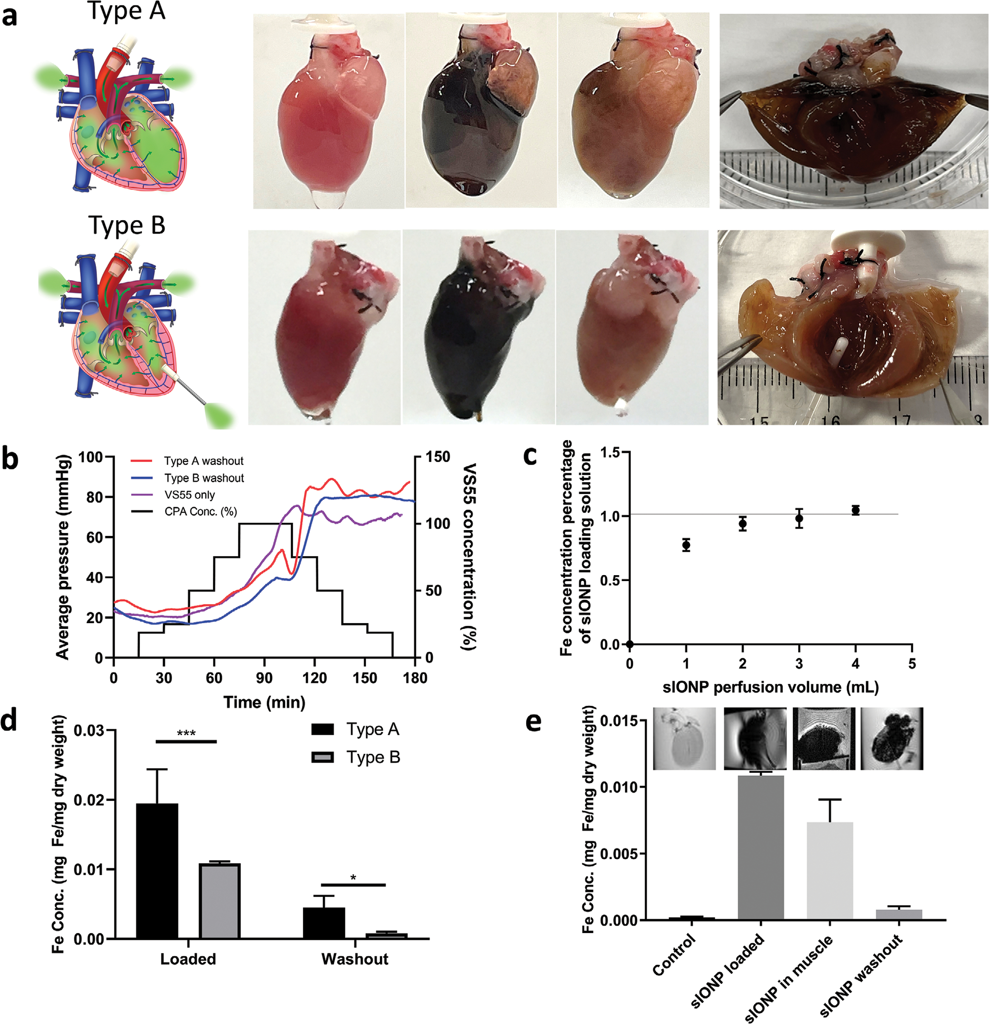
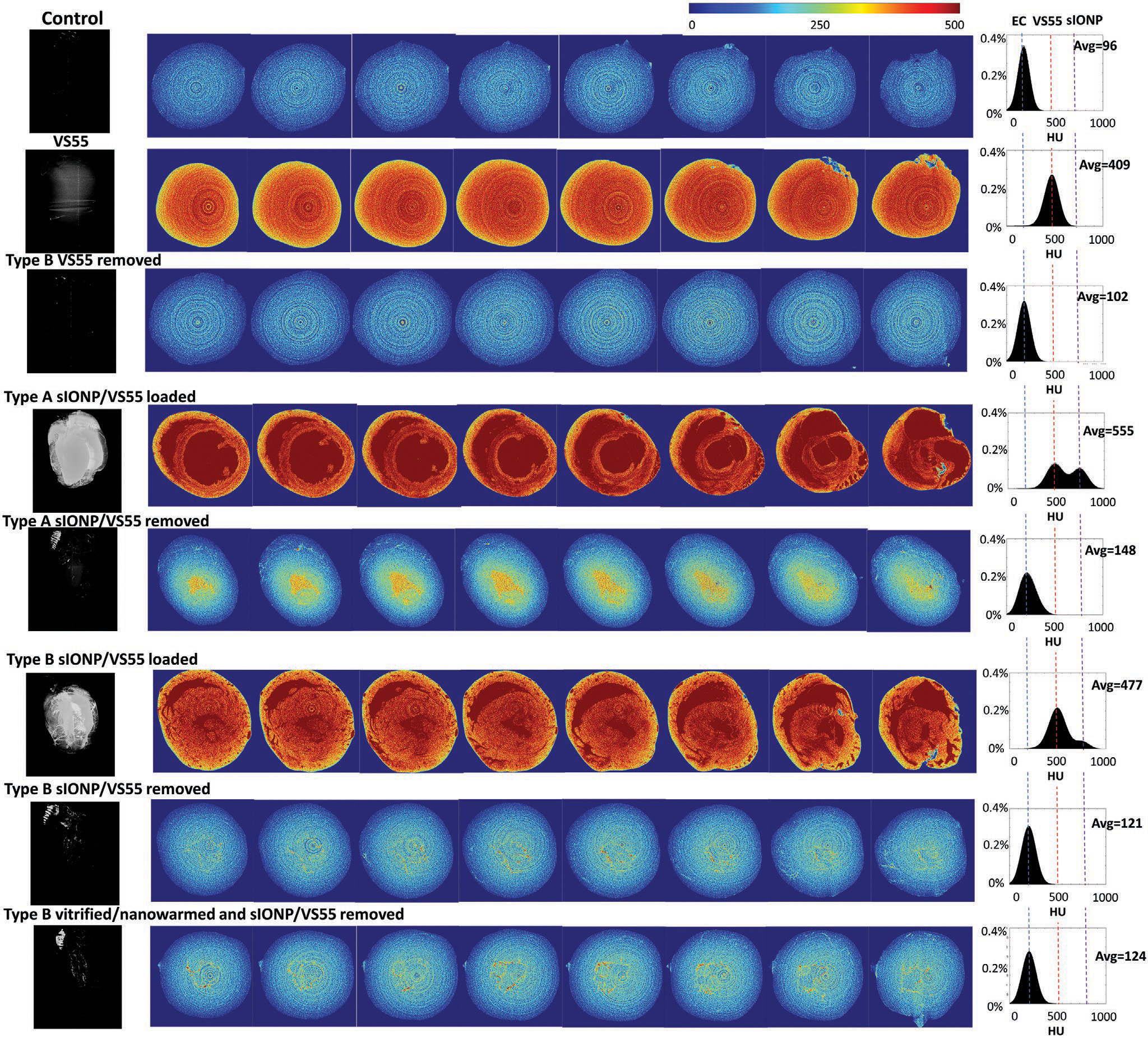
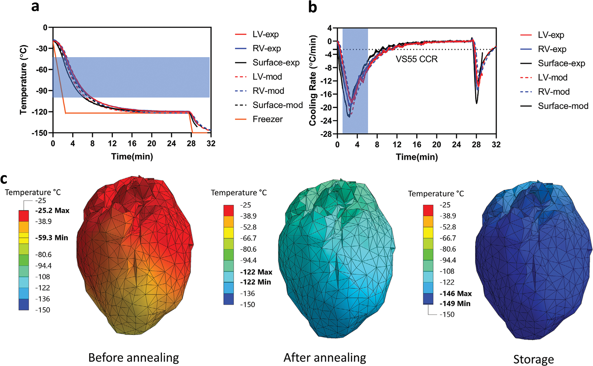
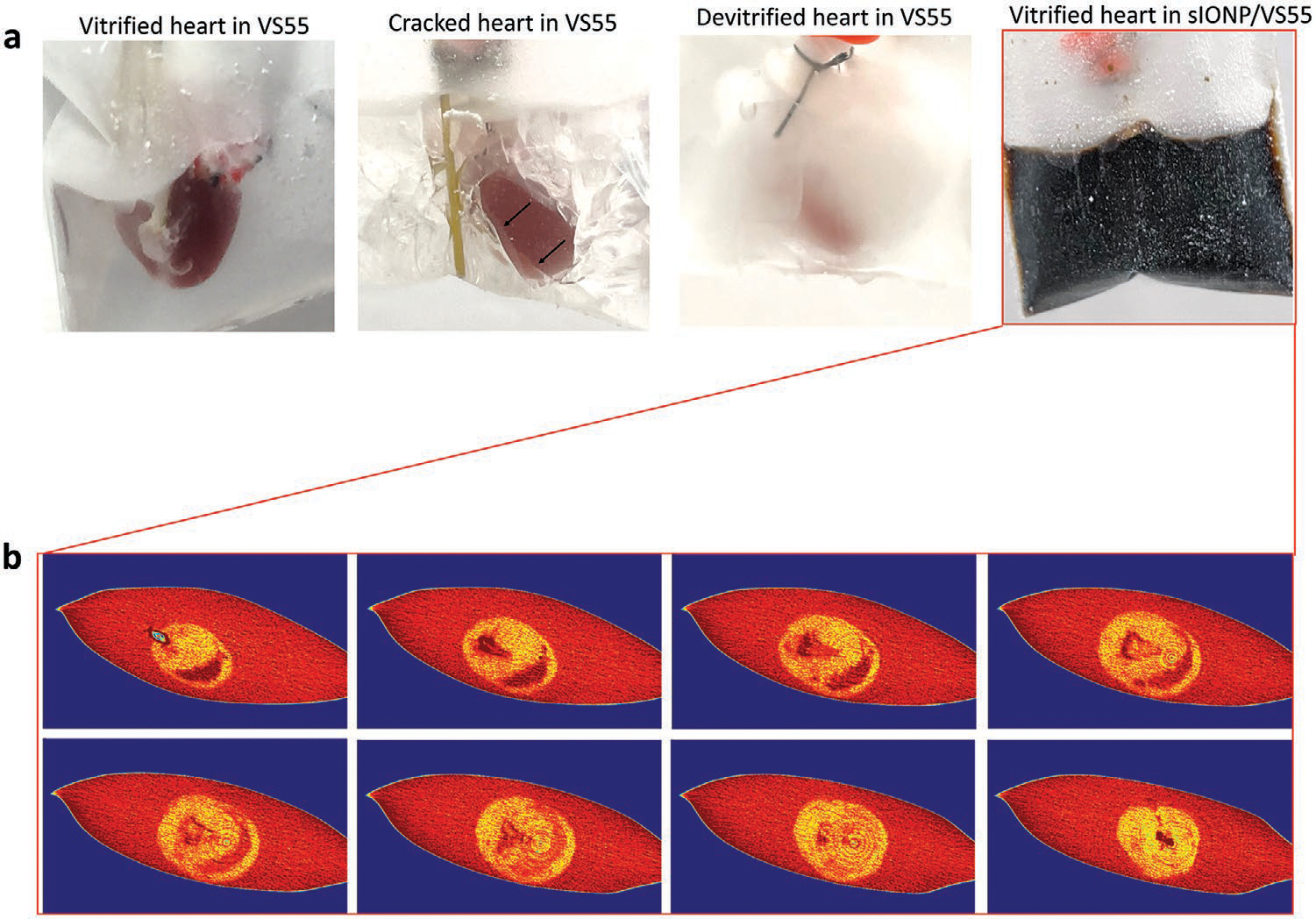
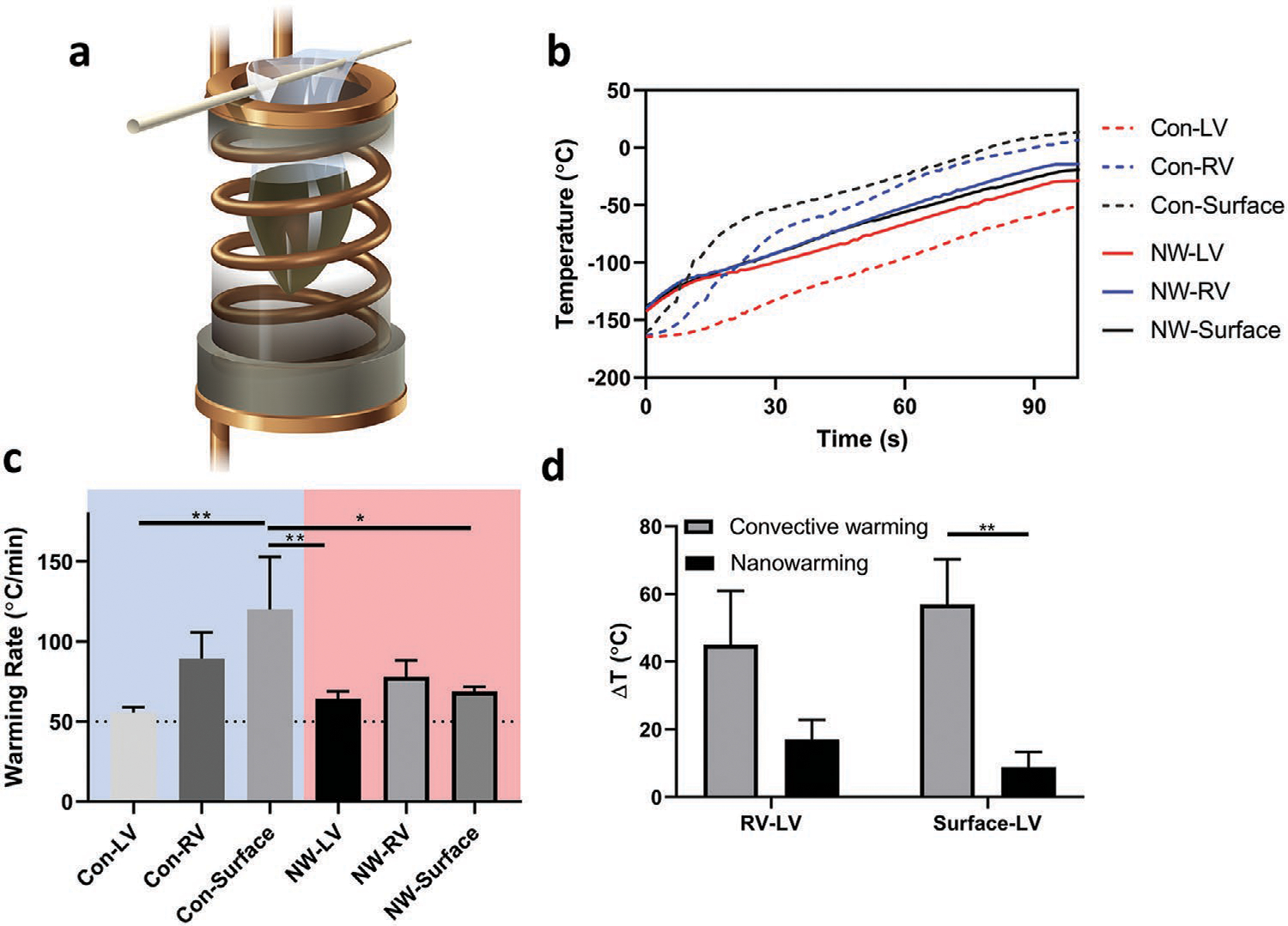
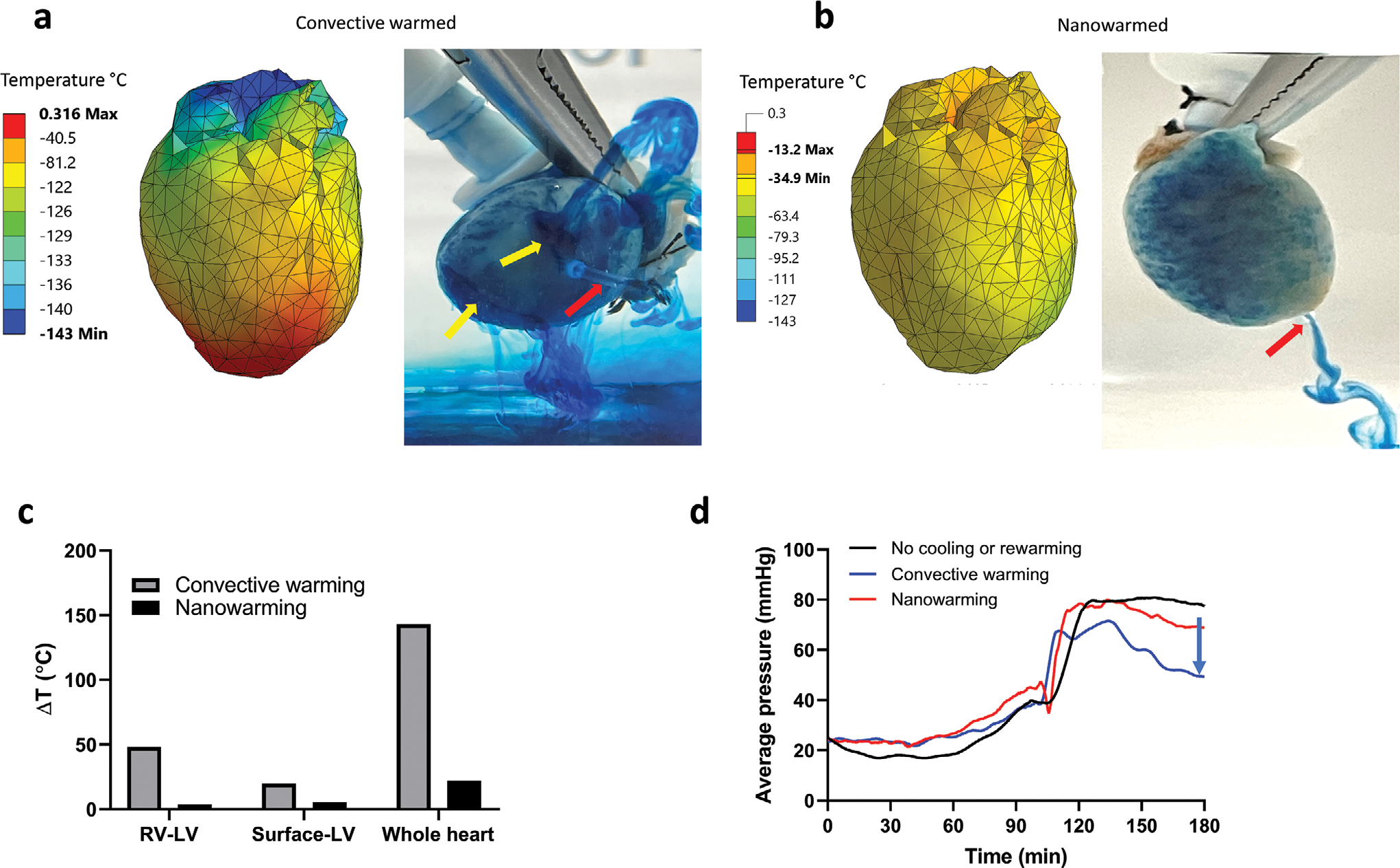
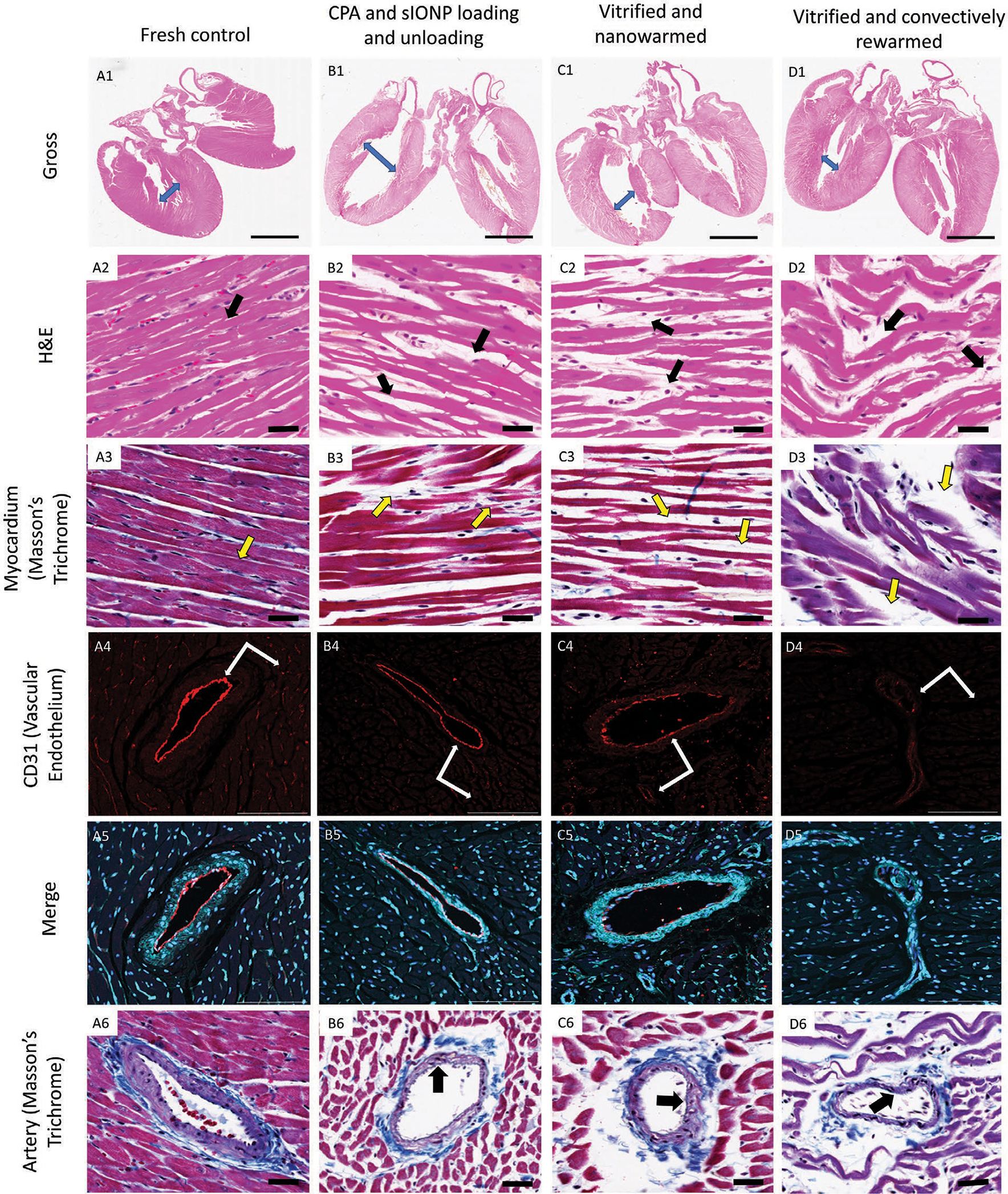
To extend the preservation of donor hearts beyond the current 4-6 h, this paper explores heart cryopreservation by vitrification-cryogenic storage in a glass-like state. While organ vitrification is made possible by using cryoprotective agents (CPA) that inhibit ice during cooling, failure occurs during convective rewarming due to slow and non-uniform rewarming which causes ice crystallization and/or cracking. Here an alternative, "nanowarming", which uses silica-coated iron oxide nanoparticles (sIONPs) perfusion loaded through the vasculature is explored, that allows a radiofrequency coil to rewarm the organ quickly and uniformly to avoid convective failures. Nanowarming has been applied to cells and tissues, and a proof of principle study suggests it is possible in the heart, but proper physical and biological characterization especially in organs is still lacking. Here, using a rat heart model, controlled machine perfusion loading and unloading of CPA and sIONPs, cooling to a vitrified state, and fast and uniform nanowarming without crystallization or cracking is demonstrated. Further, nanowarmed hearts maintain histologic appearance and endothelial integrity superior to convective rewarming and indistinguishable from CPA load/unload control hearts while showing some promising organ-level (electrical) functional activity. This work demonstrates physically successful heart vitrification and nanowarming and that biological outcomes can be expected to improve by reducing or eliminating CPA toxicity during loading and unloading.

Keywords: cryopreservation; heart; iron oxide nanoparticle; radio frequency warming; vitrification.


Conflict of interest statement

Conflict of Interest The authors declare no conflict of interest.

Figures

Figure 1.
Figure 1.
Impact of heart cannulation method on VS55 and sIONP loading and unloading in hearts. a) Schemes of type A and type B cannulation methods. Photos of hearts from left to right: pre-sIONP loading, post-sIONP loading, and post-sIONP washout and a cut open heart post-sIONP washout. b) Average perfusion resistance pressure of type A and B hearts during sIONP loading and removal and of a type B heart during VS55 loading and removal, and the VS55 concentration of the VS55 loading steps. n = 3. c) Fe concentration in the effluent from the heart compared to the loaded sIONP Fe concentration. n = 3. d) Fe concentration of loaded (p < 0.001) and washout (p = 0.0181) type A and type B hearts. Type A loaded n = 3, Type A washout n = 6, Type B loaded n = 5, Type B washout n = 5. e) Fe concentration in control heart, sIONP-loaded heart, sIONP in muscle, and sIONP washed-out type B heart. Control n = 7, sIONP loaded n = 5, sIONP in muscle n = 3, sIONP washout n = 5. The upper images are the corresponding T2*-weighted GRE MRI images. The dark lines in the image are the Teflon scaffold used to secure the heart. p < 0.0001 for all group comparison except control versus washout.
Figure 2.
Figure 2.
Microcomputed tomography (μCT) images of experimental and control heart groups. From top to bottom: a control heart perfused with EC, a heart perfused with VS55, A type B heart after VS55 removal, a type A heart perfused with VS55 and sIONP, a type A heart after removal steps, a type B heart perfused with VS55 and sIONP, a type B heart after removal steps, and a type B heart after vitrification/nanowarming and removal steps. The left column is μCT images of hearts in HU 500–800 indicating the sIONP distribution in the hearts. The center column is μCT images of heart cross sections in HU 0–500, where the VS55 could be distinguished from EC and the residue of sIONPs could be detected in this HU region. The right column is the histograms of the μCT from all cross sections for each case. The x-axis is HU, and the y-axis is the percentage of total pixels. The signal from EC, VS55, and sIONP could be distinguished as shown in the histograms. The μCT data showed left ventricle distension in the type A heart. The type B heart showed better washout comparing to the type A heart.
Figure 3.
Figure 3.
Experimental and modeling data for successfully cooled hearts. a) Measured thermal history by the three probes placed during experimentation, compared with computer simulation results at the same locations (i.e., modeling). The control rate freezer temperature was held at −122 °C (1 °C higher than the Tg) for 25 min as the annealing step (orange line in the plot), when the temperature throughout the heart equilibrated before reaching Tg. b) Experimental and calculated cooling rates for the probes presented in (a). The blue region indicates the temperature region for particular danger from ice growth (−100 to −40 °C). c) Color map representing the temperature distribution of a heart during cooling. From left to right: the cooling chamber reached the temperature of −122 °C (before annealing), after thermal equilibration at −122 °C (after annealing), and close to equilibrium around −150 °C (storage).
Figure 4.
Figure 4.
Gross and μCT images of success and failure of cooled hearts. a) Photos of vitrified (transparent), cracked (arrows show the cracks) and devitrified (white indicates ice formation) hearts in VS55 and a vitrified heart in sIONP/VS55. b) μCT images of a sIONP/VS55 loaded heart vitrified in sIONP/VS55. No crack or ice crystal was observed in the μCT cross sections of the vitrified heart after cooling in sIONP/VS55. The cross-sections are taken from bottom to top, and the displacement between the two cross-sections is 1.33 mm in the z-direction.
Figure 5.
Figure 5.
Experimental setup and data showing fast and uniform warming rates with nanowarming in comparison to convective warming. a) Illustration of a sample rewarmed in a RF coil. b) Temperature profiles of representative convectively warmed and nanowarmed hearts. The temperature difference which drives thermal stress was larger in convectively rewarmed heart than the nanowarmed heart. c) Warming rate in convectively warmed and nanowarmed hearts. n = 3. d) Maximum temperature difference between the fiber optic probes during rewarming in convectively warmed hearts and nanowarmed hearts. n = 3. Legends: Con-LV (convectively cooled left ventricle), Con-RV (convectively cooled right ventricle), Con-surface (convectively cooled heart surface). NW-LV (nanowarmed left ventricle), NW-RV (nanowarmed right ventricle), and NW Surface (nanowarmed heart surface).
Figure 6.
Figure 6.
Computational modeling supports nanowarming success and convective failure during rewarming. a) Computer simulation results of a convectively rewarmed heart. The heart was shown to have cracks as indicated by the yellow arrows identifying sources of leaking methylene blue in addition to the catheter drainage (red arrow) during Type B perfusion. b) Computer simulation results of a nanowarmed heart. The photo shows an intact heart during methylene blue with a red arrow identifying the catheter in the left ventricle during Type B perfusion. c) Maximum temperature differences between right ventricle (RV), LV (left ventricle), surface-LV, and across the whole heart predicted by modeling. d) Comparison of average perfusion resistance pressure in a control heart (no cooling or warming), convectively warmed, and nanowarmed hearts. The convectively rewarmed heart showed lower perfusion pressure indicated by the blue arrow and likely indicating vascular leakage due to cracks.
Figure 7.
Figure 7.
Histology and confocal imaging characterization. A1–D1) Gross histology of the heart on H&E comparing wall thickness and chamber volumes. Length of arrows represents the dilatation of chambers in comparison to control heart. A2–D2, A3–D3) Cardiac muscle stained with H&E and Masson’s trichrome. Arrows represent the separation of muscle fibers in all treatment groups. Conventional cryopreserved hearts represent extensive muscle disruption suggesting significant damage to tubular myofibrils and sarcomeres inhibiting intercalated disks transmitting electrical action potential between sarcomeres in contrast to vitrified-nanowarmed hearts (33.6×). A4–D4) CD31 labeled arterial endothelium in the left ventricle using fluorescence confocal microscopy. Arrows represent the integrity of the vascular endothelium in large arteries and intact smaller vasculature in the heart. Significant disruption of endothelial integrity in conventional cryopreserved hearts (20×). A5–D5) Merged confocal microscopy labeling vascular endothelium (CD31: red), galactose-α−1,3-galactose (cyan) representing carbohydrates (glycans) over the surface of muscles and blood vessels giving an architectural background and DAPI (blue) representing nuclear morphology (20×). A6–D6) Large arterial branches in the left ventricle stained with Masson’s trichrome (muscle: red; nuclei: deep blue; collagen: blue). Arrows representing arterial collagen matrix thickness alterations across treatment groups (33.6×).

Similar articles

Cited by

References

    1. Colvin M, Smith J, Hadley N, Skeans M, Uccellini K, Goff R, Foutz J, Israni A, Snyder J, Kasiske B, Am. J. Transplant. 2020, 20, 340; - PubMed
    2. Tolboom H, Makhro A, Rosser BA, Wilhelm MJ, Bogdanova A, Falk V, Eur. J. Cardio-Thorac. Surg. 2015, 47, 173. - PubMed
    1. United Network for Organ Sharing (UNOS) data, https://unos.org/data/ (accessed: December 2019).
    1. Jahania MS, Sanchez JA, Narayan P, Lasley RD, Mentzer RM Jr., Ann. Thorac. Surg. 1999, 68, 1983. - PubMed
    1. Nutt M, Fields B, Sebree L, Southard J, Pyzalska D, Pyzalski R, Thomas A, Mentzer R Jr., Bianco J, Circulation 1992, 86, II333; - PubMed
    2. Okada K, Yamashita C, Okada M, Okada M, Ann. Thorac. Surg. 1995, 60, 1723. - PubMed
    1. Ely D, Dunphy G, Dollwet H, Richter H, Sellke F, Azodi M, Free Radicals Biol. Med. 1992, 12, 479. - PubMed

LinkOut - more resources