. 2023 Mar;41(3):546-554.
doi: 10.1002/jor.25393. Epub 2022 Jun 21.

Biomechanical guidance can improve accuracy of reduction for intra-articular tibia plafond fractures and reduce joint contact stress

Affiliations

Biomechanical guidance can improve accuracy of reduction for intra-articular tibia plafond fractures and reduce joint contact stress

Michael C Willey et al. J Orthop Res. 2023 Mar.

Abstract

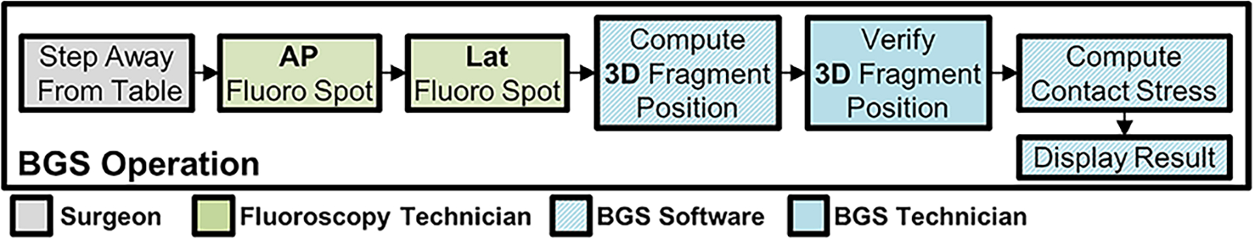
Articular fracture malreduction increases posttraumatic osteoarthritis (PTOA) risk by elevating joint contact stress. A new biomechanical guidance system (BGS) that provides intraoperative assessment of articular fracture reduction and joint contact stress based solely on a preoperative computed tomography (CT) and intraoperative fluoroscopy may facilitate better fracture reduction. The objective of this proof-of-concept cadaveric study was to test this premise while characterizing BGS performance. Articular tibia plafond fractures were created in five cadaveric ankles. CT scans were obtained to provide digital models. Indirect reduction was performed in a simulated operating room once with and once without BGS guidance. CT scans after fixation provided models of the reduced ankles for assessing reduction accuracy, joint contact stresses, and BGS accuracy. BGS was utilized 4.8 ± 1.3 (mean ± SD) times per procedure, increasing operative time by 10 min (39%), and the number of fluoroscopy images by 31 (17%). Errors in BGS reduction assessment compared to CT-derived models were 0.45 ± 0.57 mm in translation and 2.0 ± 2.5° in rotation. For the four ankles that were successfully reduced and fixed, associated absolute errors in computed mean and maximum contact stress were 0.40 ± 0.40 and 0.96 ± 1.12 MPa, respectively. BGS reduced mean and maximum contact stress by 1.1 and 2.6 MPa, respectively. BGS thus improved the accuracy of articular fracture reduction and significantly reduced contact stress. Statement of Clinical Significance: Malreduction of articular fractures is known to lead to PTOA. The BGS described in this work has potential to improve quality of articular fracture reduction and clinical outcomes for patients with a tibia plafond fracture.

Keywords: biomechanical guidance; computer-assisted surgery; intra-articular fracture; post-traumatic osteoarthritis.


Figures

Figure 1:
Figure 1:
Physical calibration object used with the BGS (left) and appearance of the calibration objects in anterior-posterior (AP – middle) and lateral (right) fluoroscopic views of a fractured cadaveric ankle specimen. The calibration object was made using a computer numerical controlled mill (Haas Automation, Oxnard, CA) and the bead spacing was confirmed to be accurate within ±25μm using a laser scanner (FARO Scan Arm® HD, FARO Technologies, UK). The angled position of the acrylic pieces containing the X and circle were chosen to be visible in these imaging planes and to surround the ankle in the surgical field without interfering with the operation.
Figure 2:
Figure 2:
Layout of the operating room including the necessary BGS components. For this simulated surgery, the ankle was mounted to a holding device and the calibration object was placed under the blue surgical drape. The specimen was imaged with the C-arm and a computer workstation (not pictured) was used to compute BGS results and display the 3D geometry and contact stress results on a large screen display.
Figure 3:
Figure 3:
Sequence of events when BGS is run. The operating surgeon requests additional data and steps back from the patient to ensure no motion occurs between AP and lateral fluoroscopy images. Once the bi-plane images are acquired, the BGS technician proceeds with automated alignment of 3D fragment positions. This is verified manually, and semi-automated corrections are performed by the technician. Contact stress is then computed automatically by the BGS software, and results are displayed to the surgeon.
Figure 4:
Figure 4:
CT volumetric renderings of the five fractured cadaver ankles reconstructed in this work. Two-, three-, and four-fragment fractures were created with an osteotome and mallet. Case four had complete separation of the articular surface from the diaphysis of the tibia.
Figure 5:
Figure 5:
General procedure and workflow of BGS. In surgical preparation, the BGS technician initializes the system and loads pre-op CT data. Immediately prior to reduction, the BGS is run once to provide 3D data to the clinician. The clinician then proceeds with the operation as normal. If at any point additional information is desired, the BGS is run (Steps 1–3) and displayed to the surgeon. Upon definitive fixation, the BGS is run to verify reduction quality.
Figure 6:
Figure 6:
Gold standard (from CT) and navigation based (from BGS) contact stress distributions were compared by parameterizing the articular surface. Contact stress was projected to a 10×10 grid and mean stress within the cell is recorded. For display purposes stress values are illustrative only.
Figure 7:
Figure 7:
Illustrative agreement between contact stress distributions generated from the post-operative CT (gold standard) and the final BGS results following definitive fixation. Example BGS trials shown include both those resulting from when the BGS data was and was not displayed to the surgeon. Visually, contact stress results compare well between the BGS-derived and post-operative CT scan-derived gold standard contact stress distributions.
Figure 8:
Figure 8:
Final contact stress metrics with and without use of BGS guidance; mean and maximum contact stress were reduced with the BGS in all four ankles that were successfully reduced and fixed.
Figure 9:
Figure 9:
Contact area engagement of all cases with BGS display versus without. Cases which received display have lower contact area at contact stress magnitudes known to be deleterious.

References

    1. Graves ML. The value of preoperative planning. J Orthop Trauma Oct 2013;27 Suppl 1:S30–4. doi:10.1097/BOT.0b013e3182a52626 - DOI - PubMed
    1. Marsh JL, Weigel DP, Dirschl DR. Tibial plafond fractures. How do these ankles function over time? J Bone Joint Surg Am Feb 2003;85-A(2):287–95. - PubMed
    1. Yablon IG, Segal D, Leach RE. Ankle injuries Churchill Livingstone; 1983:ix, 268 p.
    1. Stufkens SAS, van den Bekerom MPJ, Kerkhoffs GMMJ, Hintermann B, van Dijk CN. Long-term outcome after 1822 operatively treated ankle fractures: A systematic review of the literature. Injury-International Journal of the Care of the Injured Feb 2011;42(2):119–127. doi:10.1016/j.injury.2010.04.006 - DOI - PubMed
    1. Capo JT, Kinchelow T, Orillaza NS, Rossy W. Accuracy of fluoroscopy in closed reduction and percutaneous fixation of simulated Bennett’s fracture. Comparative Study. J H and Surg Am Apr 2009;34(4):637–41. doi:10.1016/j.jhsa.2008.12.023 - DOI - PubMed

Publication types