Numerical study of different shape design of piston bowl for diesel engine combustion in a light duty single-cylinder engine
- PMID: 35677406
- PMCID: PMC9167984
- DOI: 10.1016/j.heliyon.2022.e09602
Numerical study of different shape design of piston bowl for diesel engine combustion in a light duty single-cylinder engine
Abstract
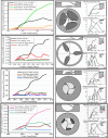
Diesel engine is the prime mover on land transportation industry and used in a variety of power generation applications due to their higher fuel efficiency. However, the engine research community faces a major hurdle rigorous restriction introduced in the Glob to reduce pollutant emissions from internal combustion engines. Different piston bowl shape designs allows more precise mixing before combustion to enhance in the optimization using computational calculations to reduce emissions. The investigation was to reduce the NOx and PM emissions using combustion simulation comparing with each piston of a single-cylinder engine at a CR of 24, 4-stroke, and water-cooled Engine. The four piston bowl shapes of DSEVL2 BMW M47T, Shallow Hesselman, Lombardini 15LD350, and DOOSANP158FE were analyzed by the Diesel-RK combustion simulation. After successful validating; the simulation model shows that the peak cylinder pressure of Piston-2 is 131bar and the peak cylinder pressure of Piston-4 is 113bar. The Maximum Cylinder Temperature of the Piston-2 is 2048.2k, and the lowest value of Cylinder Temperature of the Piston-4 is 1680.9k the cylinder temperature of Piston-2 is 18% higher than Cylinder Temperature of Piston-4. The simulation result indicates that the temperature is within the acceptable limit in between 1400-2000k except for the piston temperature of 2048.2k. The PHRR of the Piston-3 is 0.082 with great variation in between maximum and minimum due to the presence of pre-and post-injection, the HRR-P4 is 0.035 J/°CA with the single injections. The HRR of the Piston-3 is the highest while HRR of the Piston-4 lowest with 39%. The NOx in the exhaust gas is 25.62 in the NOx piston-1; 16 in NOx of Piston-2, 18.2 in NOx-P3, and NOx-P4 is 12.74 g/kWh respectively. The NOx of the NOx-P2 is lower than first and second piston due to the lower fuel fraction of NWF dilution outer the sleeve, low fuel fraction in core of the free spray, low fuel fraction in fronts of the free spray, low fuel fraction in the core of the fuel free spray. The Particulate Matter emission in PM-P1 is 0.35, and PM-P2 is 0.43 g/kWh which is higher than all the other. Although there is a substantial decrease in PM, a penalty in NOx is observed for PM-P1 but PM of the P2 is higher after the peak result of emission.
Keywords: Conventional diesel combustion; Emissions; Heat release rate; Oxides of nitrogen; Particulate matter; Piston bowl shape design.
© 2022 The Author(s).
Conflict of interest statement
The authors declare no conflict of interest.
Figures


References
-
- Abani N., Kokjohn S., Park S.W., Bergin M., Munnannur A., Ning W., Sun Y., Reitz R.D. An improved spray model for reducing numerical parameter dependencies in diesel engine CFD simulations. SAE Tech. Paper. 2008;2008(724):776–790.
-
- Ahmadi R., Hosseini S.M. Numerical investigation on adding/substituting hydrogen in the CDC and RCCI combustion in a heavy duty engine. Appl. Energy. 2018;213(x):450–468.
-
- Armin M., Gholinia M., Pourfallah M., Akbar A. Investigation of the fuel injection angle/time on combustion , energy , and emissions of a heavy-duty dual-fuel diesel engine with reactivity control compression ignition mode. Energy Rep. 2021;7:5239–5247.
-
- Banack B., Service A.H. Inject. Data. 2013;184(September):243–253.
-
- Bawankar C.S., Gupta R. 2016. Effects of Piston Bowl Geometry on Combustion and Emission Characteristics on Diesel Engine: A Cfd Case Study.
LinkOut - more resources
Full Text Sources

