Review
. 2022 Jun 2;27(11):3574.
doi: 10.3390/molecules27113574.

Molecular Modeling in Anion Exchange Membrane Research: A Brief Review of Recent Applications

Affiliations
Review

Molecular Modeling in Anion Exchange Membrane Research: A Brief Review of Recent Applications

Mirat Karibayev et al. Molecules. .

Abstract

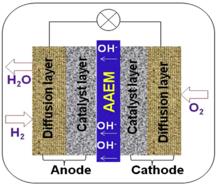
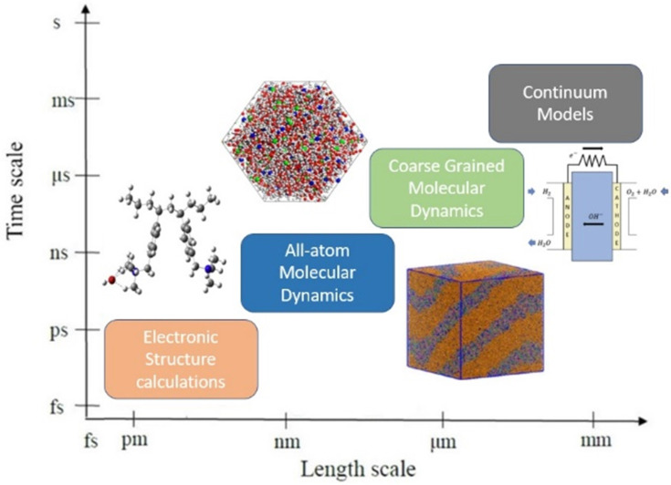
Anion Exchange Membrane (AEM) fuel cells have attracted growing interest, due to their encouraging advantages, including high power density and relatively low cost. AEM is a polymer matrix, which conducts hydroxide (OH-) ions, prevents physical contact of electrodes, and has positively charged head groups (mainly quaternary ammonium (QA) groups), covalently bound to the polymer backbone. The chemical instability of the quaternary ammonium (QA)-based head groups, at alkaline pH and elevated temperature, is a significant threshold in AEMFC technology. This review work aims to introduce recent studies on the chemical stability of various QA-based head groups and transportation of OH- ions in AEMFC, via modeling and simulation techniques, at different scales. It starts by introducing the fundamental theories behind AEM-based fuel-cell technology. In the main body of this review, we present selected computational studies that deal with the effects of various parameters on AEMs, via a variety of multi-length and multi-time-scale modeling and simulation methods. Such methods include electronic structure calculations via the quantum Density Functional Theory (DFT), ab initio, classical all-atom Molecular Dynamics (MD) simulations, and coarse-grained MD simulations. The explored processing and structural parameters include temperature, hydration levels, several QA-based head groups, various types of QA-based head groups and backbones, etc. Nowadays, many methods and software packages for molecular and materials modeling are available. Applications of such methods may help to understand the transportation mechanisms of OH- ions, the chemical stability of functional head groups, and many other relevant properties, leading to a performance-based molecular and structure design as well as, ultimately, improved AEM-based fuel cell performances. This contribution aims to introduce those molecular modeling methods and their recent applications to the AEM-based fuel cells research community.

Keywords: anion exchange membrane; chemical stability; fuel cell; modeling; multi-scale; transportation mechanism.


Conflict of interest statement

The authors declare no conflict of interest.

Figures

Figure 1
Figure 1
Schematic illustration of the working principle of AEMFCs. Reprinted with permission from [19]. Copyright 2015, for Elsevier.
Figure 2
Figure 2
(a) Possible degradation mechanisms of the QA head groups in alkaline conditions, such as Hofmann elimination (E2), nucleophilic substitution (SN2), and ylide formation (Y); (b) the five transportation mechanisms of OH ion in AEM. Reprinted with permission from [34,35]. Copyright 2017, for John Wiley and Sons, [34] and copyright 2018, for Elsevier [35].
Figure 3
Figure 3
The level of hierarchy from the atomic scale to the system level. Reprinted with permission from [50,51,52,53]. Copyright 2016, for Elsevier [50], copyright 2017, for the American Chemical Society [51], copyright 2014, for the American Chemical Society [52], and copyright 2017, for Elsevier [53].
Figure 4
Figure 4
Free energy diagram for the nucleophilic addition–elimination pathway for the benzimidazolium-based head group (unit: kcal/mol). Reprinted, with permission from [110]. Copyright 2014, for the American Chemical Society.
Figure 5
Figure 5
Degradation mechanism of N-methylpiperidine (NMP)-based AEM: (i) NMP head group detachment, (ii) ring-opening with subsequent formation of alkene, and (iii) ring-opening via direct hydroxylation. Reprinted with permission from [117]. Copyright 2020, for John Wiley and Sons.
Figure 6
Figure 6
The detailed z-axis illustration of vehicular diffusion mechanism steps (ah). Representative configurations showing the vehicular diffusion for the simulated system from a z-axis perspective, in the center of the cell (ad) and in the bottleneck region (eh), including five water molecules from the first and second solvation shells. Red, white, turquoise, and blue spheres represent O, H, C, and N atoms, respectively. A green sphere represents the hydroxide ion. (a) A hydroxide ion is in a stable threefold structure near a cation, with two water molecules in the second solvation shell. (b) The hydroxide ion is in a fourfold planar structure in the center of the cell, with one water molecule in the second solvation shell. (c) The hydroxide ion and the five water molecules move toward the nearby cation. (d) The hydroxide ion is in a stable threefold structure near a cation. Two water molecules are located at neighboring bottleneck regions. (e) The hydroxide ion forms a stable OH(H2O)4 complex, in which three water molecules are part of a threefold tetrahedral structure, and one water molecule is in the second solvation shell. A water molecule is located below the hydroxide ion in the bottleneck region. (f) The hydroxide ion and five water molecules are diffusing through the bottleneck region. (g) The hydroxide ion crosses the bottleneck region and is located near a cation in a stable threefold structure. (h) The hydroxide ion’s threefold structure changes back into a fourfold planar structure, as it diffuses toward the center of the cell. Reprinted with permission from [41]. Copyright 2019, for the American Chemical Society.
Figure 7
Figure 7
The various configurations for designed distribution of water in AEM at the different axis. Green and yellow spheres represent the initial and final hydroxide ion oxygen atoms, respectively. (A,B) OH exhibits vehicular diffusion at room temperature, forming a stable OH(H2O)5 complex, in which three water molecules are part of a threefold tetrahedral structure (with one water molecule located below the hydroxide in the bottleneck region, while two water molecules are in the second solvation shell. (C,D) The hydroxide ion is trapped in the center of the cell at 350 K, as a result of a proton rattling event. (E,F) OH exhibits vehicular diffusion along the x-axis at 400 K, forming a twofold structure, as a result of the increased mobility of the water molecules. (G,H) OH exhibits diffusion along the y-axis at 400 K, due to the high mobility of the water molecules. The hydroxide ion diffuses via vehicular diffusion toward the bottleneck region; a proton-transfer event, then, occurs in the bottleneck region, which places the nascent hydroxide into the center of the cell. Reprinted with permission from [43]. Copyright 2022, for the American Chemical Society.
Figure 8
Figure 8
Key elements of machine learning in materials science. (a) Schematic view of an example dataset, (b) statement of the learning problem, and (c) creation of a surrogate prediction model, via the fingerprinting and learning steps. N and M are, respectively, the number of training examples and the number of fingerprint (or descriptor or feature) components. Reprinted with permission from [162]. Copyright 2017, for Springer Nature.
Figure 9
Figure 9
(A) Snapshot of hydrated M1 membrane with water channels illustrated by isosurfaces, corresponding to 50% of bulk water density. (B) Distribution of water channel width. (C) Blue spheres illustrate the locations of the “bottlenecks” inside water channels. (D) Illustration of correspondence of membrane morphologies obtained from the APPLE&P simulation and mapped to ReaxFF. The red chain shows a polymer backbone for the selected chain in the APPLE&P simulation, while the green chain shows the same chain after mapping and relaxation in ReaxFF simulation. Reprinted with permissions from [36]. Copyright 2020, for the American Chemical Society.
Figure 10
Figure 10
(a) Bead-based visualization of a simulated PPO-Q system (degree of functionality: 20%, water uptake: 20 wt%, ion exchange capacity: 1.48). Cyan beads are water beads (type W), and orange beads are polymer beads (type B). (b) Isosurface around the W beads visually illustrating the water domain. (c) Radial distribution function of W beads; the location at which the first peak drops below 1 is 1.2 nm. The inset shows the isosurface of W beads in the clipped bottom of the simulation box. Reprinted with permissions from [177]. Copyright 2020, for the American Chemical Society.
Figure 11
Figure 11
A schematic representation of AEMFC. Reprinted with permission from [53]. Copyright 2017, for Elsevier.

Similar articles

Cited by

References

    1. Kober T., Schiffer H.W., Densing M., Panos E. Global energy perspectives to 2060–WEC’s World Energy Scenarios 2019. Energy Strategy Rev. 2020;31:100523. doi: 10.1016/j.esr.2020.100523. - DOI
    1. Dutta S. A review on production, storage of hydrogen and its utilization as an energy resource. Ind. Eng. Chem. Res. 2014;20:1148–1156. doi: 10.1016/j.jiec.2013.07.037. - DOI
    1. Spiegel C. Designing and Building Fuel Cells. Volume 87 McGraw-Hill Professional; New York, NY, USA: 2007.
    1. Breeze P. Fuel Cells. 1st ed. Academic Press; Cambridge, MA, USA: 2017.
    1. Xiao F., Wang Y.C., Wu Z.P., Chen G., Yang F., Zhu S., Siddharth K., Kong Z., Lu A., Li J.C., et al. Recent advances in electrocatalysts for proton exchange membrane fuel cells and alkaline membrane fuel cells. Adv. Mater. 2021;33:2006292. doi: 10.1002/adma.202006292. - DOI - PubMed

LinkOut - more resources