. 2022 May 27;22(11):4069.
doi: 10.3390/s22114069.

Wearable Sensor Based on Flexible Sinusoidal Antenna for Strain Sensing Applications

Affiliations

Wearable Sensor Based on Flexible Sinusoidal Antenna for Strain Sensing Applications

Mehran Ahadi et al. Sensors (Basel). .

Abstract

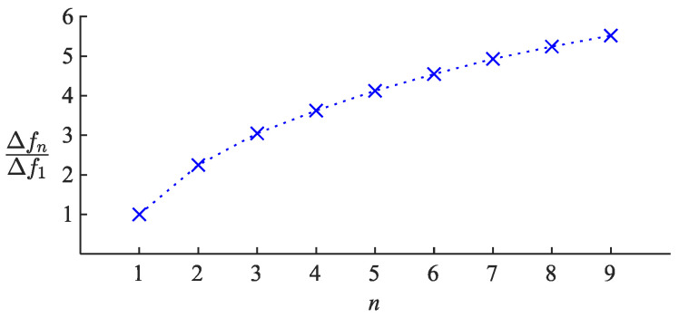
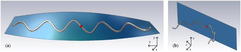
A flexible sinusoidal-shaped antenna sensor is introduced in this work, which is a modified half-wave dipole that can be used for strain sensing applications. The presented antenna is an improved extension of the previously introduced antenna sensor for respiration monitoring. The electrical and radiative characteristics of the sinusoidal antenna and the effects of the geometrical factors are studied. An approach is provided for designing the antenna, and equations are introduced to estimate the geometrical parameters based on desired electrical specifications. It is shown that the antenna sensor can be designed to have up to 5.5 times more sensitivity compared to the last generation of the antenna sensor previously introduced for respiration monitoring. The conductive polymer material used to fabricate the new antenna makes it more flexible and durable compared to the previous generation of antenna sensors made of glass-based material. Finally, a reference antenna made of copper and an antenna sensor made of the conductive polymer are fabricated, and their electrical characteristics are analyzed in free space and over the body.

Keywords: antenna sensor; conductive polymer; dipole antenna; miniaturized antenna; sinusoidal antenna; strain sensor; tunable antenna.


Conflict of interest statement

The authors declare no conflict of interest.

Figures

Figure A1
Figure A1
Correlation of the data and the equations achieved via curve fitting based on SR for (a) radiation resistance on resonance frequency (zoomed in) and (b) resonance frequency normalized to fD1. Solid lines represent the data, and dashed lines represent the fitted function. It is clear that the fitted function on RR is ambiguous for adjacent n values.
Figure A2
Figure A2
Correlation of the data and the equations achieved via curve fitting based on WR for (a) radiation resistance on resonance frequency and (b) resonance frequency normalized to fD2. Solid lines represent the data, and dashed lines represent the fitted function. (c) Correlation of the data and Equation (10), it is evident that the data are almost independent of n factor. The dashed line shows the fitted Equation.
Figure 1
Figure 1
Antenna Geometry with n=5. Small circles in the middle indicate the feeding point. The antenna is placed along Z-axis, and the peaks and dips are along the Y-axis.
Figure 2
Figure 2
Sample design of an antenna with n=3 for different values of SR. It is evident that the more the SR increases, the higher the width of the antenna.
Figure 3
Figure 3
(a) Radiation Resistance of the antenna on resonance frequency. Inset: zoomed-in detail of the crossing around the 50 Ω line. (b) The resonance frequency of the antenna normalized to the resonance frequency of the straight half-wave dipole (fD1 ).
Figure 4
Figure 4
Antennas designed for radiation resistance of 50 Ω on a specific frequency using values of 1, 5, and 9 for the n factor. The higher the n factor, the less the antenna width for the same resonance frequency and radiation resistance, resulting in a more linear structure.
Figure 5
Figure 5
Far-field radiation gain (G) pattern of the 50 Ω  sinusoidal dipole antenna for n=1,3,,9. The antenna is placed along Z-axis, and the sinusoidal peaks and dips are spread along Y-axis.
Figure 6
Figure 6
Representation of increasing WR of an example antenna with n=3, while keeping LA as constant and ignoring the fixed wire length LW constraint.
Figure 7
Figure 7
Antenna characteristics for different n values expressed versus WR while the axial length LA is kept constant (a) Radiation Resistance of the antenna on resonance frequency. The required WR values to design a 50 Ω antenna are marked for n=3,,9 (b) Resonance frequency normalized to fD2.
Figure 8
Figure 8
(a) Fabrication process of the MWCNT-PEVA conductive polymer (b) the extrusion process of the polymer wire (c) SEM image of the cross-section of the MWCNT-PEVA polymer wire.
Figure 9
Figure 9
(a) The Copper antenna (b) The Polymer antenna, sewn on a T-shirt (c) Return loss of the antenna in simulation, the Copper antenna, and the Polymer antenna, both in free space and over the body.
Figure 10
Figure 10
A 50 Ω antenna sensor n=5, embedded on a smart T-shirt for vital signal monitoring applications.
Figure 11
Figure 11
The fabric is completely submerged in water and detergent. The SMA connectors are held outside.
Figure 12
Figure 12
Antenna electrical characteristics are measured after each washing cycle. Each measurement is made four times, and the average is reported. Error bars show the standard deviation of each measurement. (a) Normalized frequency shift of the antenna. Green dashed line indicates zero shift. (b) Return Loss of the antenna on resonance frequency. (c,d) Real and Imaginary part of the antenna’s impedance on operation frequency, respectively. Green dashed line indicates the ideal values for a 50 Ω impedance matching.
Figure 13
Figure 13
Sensitivity of the resonance frequency of the sinusoidal antenna sensor to the applied strain, expressed relative to the sensitivity of the traditional antenna sensor with n=1, for antennas n>1.
Figure 14
Figure 14
Illustration of (a) the twisting and (b) the bending applied to the modeled antenna in simulation software. The blue metallic-colored plane, the thick wire, and the lighting effects are added for a better presentation of the 3D model.
Figure 15
Figure 15
(a,b) The shift in antenna’s resistance on resonance and (c,d) its normalized resonance frequency for different angles of bending and twisting, respectively.
Figure 16
Figure 16
(a) SAR for excitation of 1 mW averaged over 1 g of tissue (b) Antenna placed on the chest area (c) Cross-section of the phantom model (d) Perspective view of the phantom model.

References

    1. Kraus J.D. Antennas. 2nd ed. McGraw-Hill; New York, NY, USA: 1988. (McGraw-Hill Series in Electrical Engineering).
    1. Roudjane M., Bellemare-Rousseau S., Khalil M., Gorgutsa S., Miled A., Messaddeq Y. A Portable Wireless Communication Platform Based on a Multi-Material Fiber Sensor for Real-Time Breath Detection. Sensors. 2018;18:973. doi: 10.3390/s18040973. - DOI - PMC - PubMed
    1. Roudjane M., Bellemare-Rousseau S., Drouin E., Belanger-Huot B., Dugas M.-A., Miled A., Messaddeq Y. Smart T-Shirt Based on Wireless Communication Spiral Fiber Sensor Array for Real-Time Breath Monitoring: Validation of the Technology. IEEE Sens. J. 2020;20:10841–10850. doi: 10.1109/JSEN.2020.2993286. - DOI
    1. Guay P., Gorgutsa S., LaRochelle S., Messaddeq Y. Wearable Contactless Respiration Sensor Based on Multi-Material Fibers Integrated into Textile. Sensors. 2017;17:1050. doi: 10.3390/s17051050. - DOI - PMC - PubMed
    1. Mulholland K., Virkki J., Raumonen P., Merilampi S. Wearable RFID Perspiration Sensor Tags for Well-Being Applications—From Laboratory to Field Use. In: Eskola H., Väisänen O., Viik J., Hyttinen J., editors. EMBEC & NBC 2017. Volume 65. Springer; Singapore: 2018. pp. 1012–1015. IFMBE Proceedings.

LinkOut - more resources