. 2022 Jun 10;12(1):9577.
doi: 10.1038/s41598-022-13631-1.

Multi-modal and multi-scale clinical retinal imaging system with pupil and retinal tracking

Affiliations

Multi-modal and multi-scale clinical retinal imaging system with pupil and retinal tracking

Muhammad Faizan Shirazi et al. Sci Rep. .

Abstract

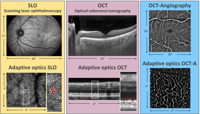
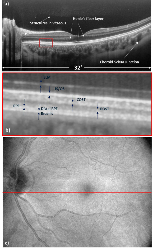
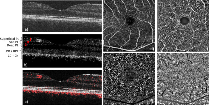
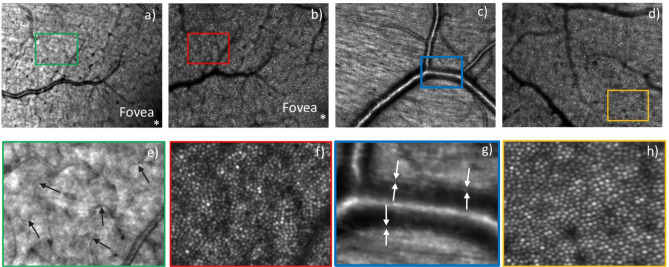
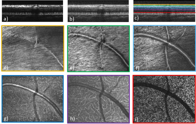
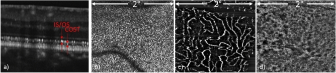
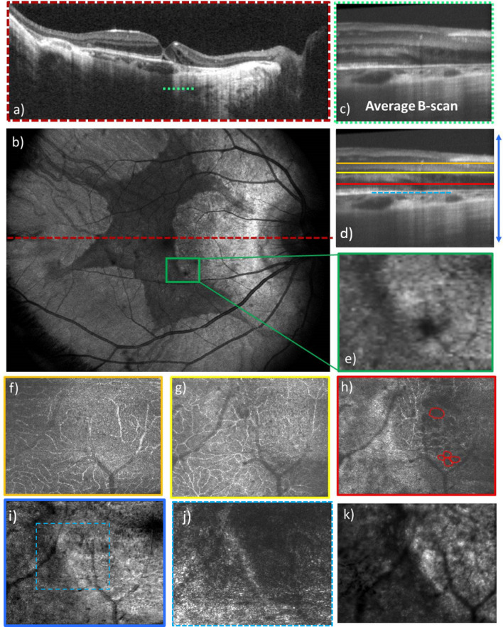
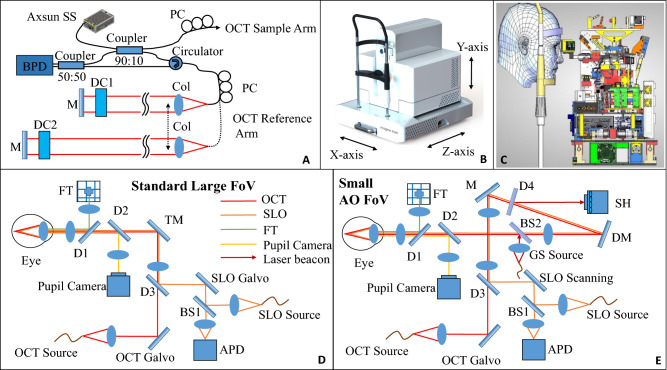
We present a compact multi-modal and multi-scale retinal imaging instrument with an angiographic functional extension for clinical use. The system integrates scanning laser ophthalmoscopy (SLO), optical coherence tomography (OCT) and OCT angiography (OCTA) imaging modalities and provides multi-scale fields of view. For high resolution, and high lateral resolution in particular, cellular imaging correction of aberrations by adaptive optics (AO) is employed. The entire instrument has a compact design and the scanning head is mounted on motorized translation stages that enable 3D self-alignment with respect to the subject's eye by tracking the pupil position. Retinal tracking, based on the information provided by SLO, is incorporated in the instrument to compensate for retinal motion during OCT imaging. The imaging capabilities of the multi-modal and multi-scale instrument were tested by imaging healthy volunteers and patients.


Conflict of interest statement

MFS, FS, CEH, AA, MEWT, ML, JA, CPV, PLA, KGr, KGo, JG, MPa, KN, DAJ, LSB, SK, TW, and MPi have no competing interests. Imagine Eyes (MD, NL, XL and NC) has financial interest in the presented work.

Figures

Figure 1
Figure 1
Overview of the multi-modal and multi-scale functionality of the instrument. The signal arising from individual cone photoreceptors is encircled in red color.
Figure 2
Figure 2
Representative OCT images recorded with the large field of view imaging mode in the healthy subject where (a) shows an average over 200 B-scans recorded at the same location, (b) shows an enlarged view of the posterior layers of the retina, and (c) shows the en-face intensity projection image of the volume scan. The red line at the center of the OCT en-face image indicates the location of the averaged B-scan image. ELM, external limiting membrane; IS/OS, inner and outer segment junction; COST, cone outer segment tips; ROST, rod outer segment tips; RPE, retinal pigment epithelium.
Figure 3
Figure 3
Representative image data recorded with the 10° × 10° field of view scanning pattern and 4 B-scans at the same location. (a) Single B-scan intensity image, (b) OCTA B-scan, (c) composite image of intensity (grey) and OCTA (red), (d) superficial vascular plexus, (e) mid vascular plexus, (f) deep vascular plexus (the integration depth of the en-face projections are indicated with the red arrows in b,g) choriocapillaris (en-face projection over three pixels below the RPE). PL plexus, PR photoreceptors, RPE retinal pigment epithelium, CC choriocapillaris, Ch choroid.
Figure 4
Figure 4
AO-SLO images of a healthy volunteer recorded with a field of view of 4° × 3°. (a) AO-SLO image from near the fovea with its focus on the nerve fiber layer and (b) the same field, now focused on the photoreceptor layer. Images (c,d) are from two different fields, centered at ~ 4° eccentricity from the fovea and focused on the nerve fiber layer and the photoreceptor layer, respectively. Figures (eh) are the 4 × enlarged view of the rectangular boxes marked in Figures (ad), respectively. The arrows in (e) indicate small capillaries while in (g) the vessel wall is marked.
Figure 5
Figure 5
AO-OCT B-scan (ac) and en-face images of different layers (di) recorded with a field of view of 4° × 3°. (a) B-scan in linear scale, (b) B-scan in log scale, (c) color-coded lines indicating the location of the corresponding en-face layers in B-scan, (d) inner limiting membrane, (e) nerve fiber layer, (f) superficial vascular plexus layer, (g) mid vascular plexus layer, (h) deep vascular plexus layer, (i) inner/outer segment junction layer.
Figure 6
Figure 6
AO-OCT and AO-OCTA images of different layers with the field of view of 2° × 2°. (a) AO-OCT B-scan in logarithmic scale, (b) AO-OCT photoreceptor mosaic en-face image, (c) AO-OCTA deep plexus en-face image, (d) AO-OCTA en-face choriocapillaris image. IS/OS inner and outer segment junction, COST cone outer segment tips.
Figure 7
Figure 7
AO-OCT and AO-SLO images of a patient with choroideremia disease with 4° × 3° field of view along with the large field of view images. (a) Average OCT large field of view B-scan in log scale, (b) OCT large field of view en-face projection image with 40° × 30° field of view, (c) average AO-OCT B-scan in log scale, (d) location of corresponding layers displayed in the en-face images, (e) large field of view en-face projection image with zoom at the location imaged with AO-OCT, (f) mid capillary plexus layer, (g) deep capillary plexus layer, (h) outer nuclear layer with red circles indicating the microcysts, (i) entire depth projection image, (j) depth projection over photoreceptor and RPE layers at the 2° × 2° field marked in (j,k) AO-SLO image of the corresponding location.
Figure 8
Figure 8
Multi-modal and multi-scale retinal imaging instrument design. (A) Schematic diagram of the OCT interferometer with two separate reference arms for the two imaging modes. (B) Three dimensional instrument design with motorized stages. (C) System architecture that shows the arrangement of different components inside the system. (D) Standard large field of view beam path for OCT, SLO, FT, pupil camera. (E) Beam path for small AO field of view mode with an additional laser beacon for wavefront measurement. This path requires only flipping the TM mirror. APD avalanche photodiode, BPD balanced photodetector, BS beam splitter, Col collimator, D dichroic mirror, DC dispersion compensating rods, DM deformable mirror, FT fixation target, GS guide star, PC polarization controller, SH Shack-Hartmann wavefront sensor.

References

    1. Webb RH, Hughes GW, Delori FC. Confocal scanning laser ophthalmoscope. Appl. Opt. 1987;26:1492–1499. doi: 10.1364/AO.26.001492. - DOI - PubMed
    1. Huang D, et al. Optical coherence tomography. Science. 1991;254:1178. doi: 10.1126/science.1957169. - DOI - PMC - PubMed
    1. Makita S, Hong Y, Yamanari M, Yatagai T, Yasuno Y. Optical coherence angiography. Opt. Express. 2006;14:7821–7840. doi: 10.1364/OE.14.007821. - DOI - PubMed
    1. de Carlo TE, Romano A, Waheed NK, Duker JS. A review of optical coherence tomography angiography (OCTA) Int. J. Retina Vitreous. 2015;1:5. doi: 10.1186/s40942-015-0005-8. - DOI - PMC - PubMed
    1. Gao SS, et al. Optical coherence tomography angiography. Investig. Ophthalmol. Vis. Sci. 2016;57:27–36. doi: 10.1167/iovs.15-19043. - DOI - PMC - PubMed

Publication types